A method and device for dynamically measuring the evolution process of a dam failure
A technology of evolution process and dynamic measurement, which is applied in the direction of measuring device, fluid dynamics test, machine/structural component test, etc. It can solve the problems of small size, excessive stress level difference between model and prototype, and inability to solve the problem of test model size, etc. , to achieve the effect of high cost
- Summary
- Abstract
- Description
- Claims
- Application Information
AI Technical Summary
Problems solved by technology
Method used
Image
Examples
Embodiment 1
[0043] A method for dynamically measuring the evolution process of a dam failure, comprising the following steps:
[0044] S1. Start the motor 10 on the device for dynamically measuring the dam break evolution process, drive the ultrasonic ranging mechanism to run up and down through the transmission mechanism, and drive the gridded laser point measuring mechanism to move back and forth;
[0045] S2. Start the external supergravity field providing device to drive the dynamic measurement of the dam break evolution process device to operate under the supergravity field, and control the water flow into the dynamic measurement dam break evolution process device through the external control system;
[0046] S3, measure the flow Q in real time through the rectangular water measuring weir 4 installed inside the dynamic measurement dam break evolution process device;
[0047] S4. Use the ultrasonic ranging mechanism to measure the change of the water head H in front of the rectangular...
Embodiment 2
[0056] Embodiment 2: the difference based on Embodiment 1 is;
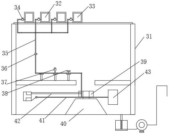
[0057] A device for dynamically measuring the evolution process of a dam failure, applied to a method for dynamically measuring the evolution process of a dam failure, comprising: a main frame 31, an automatic water flow control mechanism, and a centrifugal model test mechanism for a dam failure;
[0058] An automatic water flow control mechanism, the automatic water flow control mechanism is placed in the main frame 31, and the automatic water flow control mechanism is connected with the dam failure centrifugal model test mechanism;
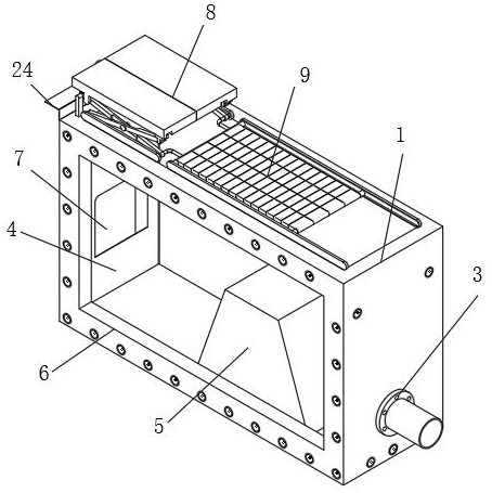
[0059] A special model box for the dam break test, the special model box for the dam break test is placed on the lower left side inside the main frame 31, and the special model box for the dam break test is connected with the automatic water flow control mechanism.
[0060] The special model box for dam break test includes: box body 1, high-strength inner screw sleeve 2, connecting ...
Embodiment 3
[0062] Embodiment 3: the difference based on embodiment 1 and 2 is;
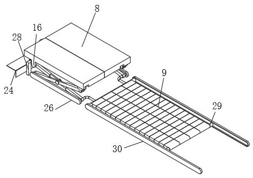
[0063] The transmission mechanism includes: motor 10, transmission gear 11, rotating gear 12, rotating shaft 13, limit gear 14, rotating half gear 15, rotating rod 17, transmission rod 18, fixed shaft 19, connecting shaft 23, mounting plate 24, limiting Position shaft 25, limit housing 26, movable shaft 27 and stabilizing column 28, a mounting plate 24 is fixedly installed on the left side of the upper end of the box body 1, a motor 10 is fixedly installed in the middle of the mounting plate 24, the front end of the main shaft of the motor 10 and the shaft center of the transmission gear 11 Fixed connection, the transmission gear 11 is meshed with the rotating gear 12, the axis of the rotating gear 12 is fixedly connected with the middle part of the rotating shaft 13, and the inner side of the left and right ends of the rotating shaft 13 is fixedly connected with the axis of the limit gear 14, and the limit g...
PUM
 Abstract
Description
Claims
Application Information
 - R&D
- Intellectual Property
- Life Sciences
- Materials
- Tech Scout
- Unparalleled Data Quality
- Higher Quality Content
- 60% Fewer Hallucinations
Browse by: Latest US Patents, China's latest patents, Technical Efficacy Thesaurus, Application Domain, Technology Topic, Popular Technical Reports.
© 2025 PatSnap. All rights reserved.Legal|Privacy policy|Modern Slavery Act Transparency Statement|Sitemap|About US| Contact US: help@patsnap.com


