
Automatic speed-cutting contact device for high-speed rail

A contact device, high-speed rail technology, applied in the direction of overhead lines, etc., can solve the problems of non-compulsory, achieve significant economic and social benefits, prevent tailing, derailment and rollover accidents, and avoid economic losses

Inactive Publication Date: 2019-06-14
彭绵杰
View PDF0 Cites 0 Cited by
  • Summary
  • Abstract
  • Description
  • Claims
  • Application Information

AI Technical Summary

Problems solved by technology

The second is that the frequency conversion and deceleration action of the train at the turning point does not have the natural law of coercion under the premise of losing human operation and control behavior.

Method used


Image

  • Automatic speed-cutting contact device for high-speed rail
  • Automatic speed-cutting contact device for high-speed rail
  • Automatic speed-cutting contact device for high-speed rail

Examples


Embodiment Construction

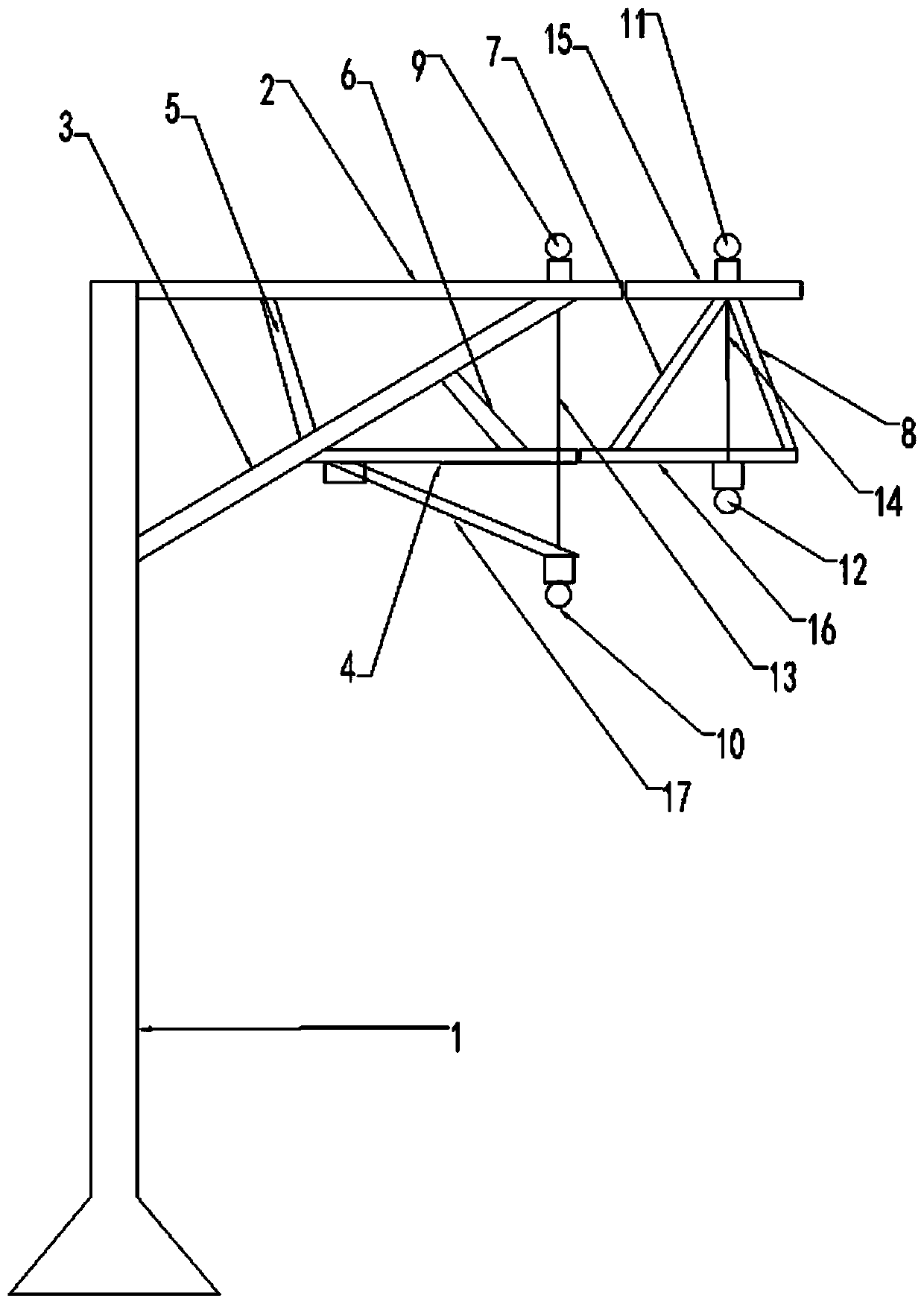
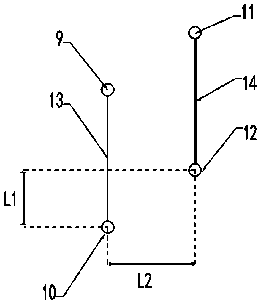
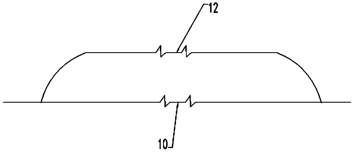
[0024] example, as Figure 1-3 As shown, an automatic deceleration type high-speed rail contact device includes a column 1, a contact wire 10 for power transmission for a high-speed train is suspended on the column 1, and a shunt wire 12 is connected in parallel on the contact wire 10 near the turn of the rail.

[0025] One side of the column 1 close to the upper end is connected to the contact line 10 and the shunt line 12 through a support device.

[0026] The support device includes a column top horizontal rod 2 fixedly connected on the top end side of the vertical column 1 , and the column top horizontal rod 2 is arranged laterally.

[0027] An inclined support rod 3 is fixedly connected between the column top horizontal rod 2 and the vertical column 1 , and a stable triangular structure is formed between the inclined support rod 3 , the column top horizontal rod 2 and the vertical column 1 .

[0028] A first oblique pull rod 5 is fixedly connected between the lower end s...


PUM


Abstract

The invention discloses an automatic speed-cutting contact device for high-speed rail, which comprises a main support body, and a contact line for electricity transmission of the high-speed train is hoisted on the main support body, and a shunt line is connected in parallel near the turning position of the rail on the contact line. The current transmitted by the automatic speed-cutting contact device for high-speed rail to the pantograph of the train is smaller; at the same time, the current transmitted to the traction motors by a traction transformer in the train after transforming voltage isalso smaller; at the same time, based on the nominal (constant) torque of each traction motor, the received current of each traction motor is decreased by 50% compared with the received current of each traction motor before the parallel connection of the contact line. Because the received current value of the motor is reduced by half, the output power of the motor is also reduced by half, and therevolving speed is also reduced by half.

Description

technical field [0001] The invention relates to a high-speed rail overhead contact device, in particular to an automatic deceleration type high-speed rail contact device, which belongs to the technical field of high-speed train automatic speed change. Background technique [0002] At present, the speed switching of the high-speed train at the corner is still performed by the operator through electronic signal input or manual operation to make the frequency conversion system perform frequency regulation, so that the traction motor can achieve the purpose of speed regulation. However, this kind of frequency conversion speed regulation method should be single for the speed control measures of the train under the condition of bending operation. This single speed control mode has a guarantee rate of less than 100% for ensuring the safe operation of the train on the curve. [0003] The disadvantages of the above single speed control method are mainly reflected in the fact that th...

Claims


Application Information

Patent Timeline
Patent Type & Authority Applications(China)
IPC IPC(8): B60M1/22
Inventor 彭绵杰
Owner 彭绵杰
Learn More