
Pneumatic tire

A technology for pneumatic tires and tires, which is applied to the reinforcement layer of pneumatic tires, motorcycle tires, tire parts, etc., which can solve the problems of easy deterioration of rim fit and difficult bead fit, etc., to improve fit And the effect of steering stability performance, fit improvement, steering stability performance improvement

Active Publication Date: 2019-06-14
SUMITOMO RUBBER IND LTD
View PDF10 Cites 1 Cited by
  • Summary
  • Abstract
  • Description
  • Claims
  • Application Information

AI Technical Summary

Problems solved by technology

[0003] However, such a pneumatic tire has a problem that it is difficult to fit the bead portion to the rim, and the fitting performance with the rim tends to deteriorate.

Method used


Image

  • Pneumatic tire
  • Pneumatic tire
  • Pneumatic tire

Examples


Embodiment Construction

[0020] Hereinafter, one embodiment of the present invention will be described based on the drawings.

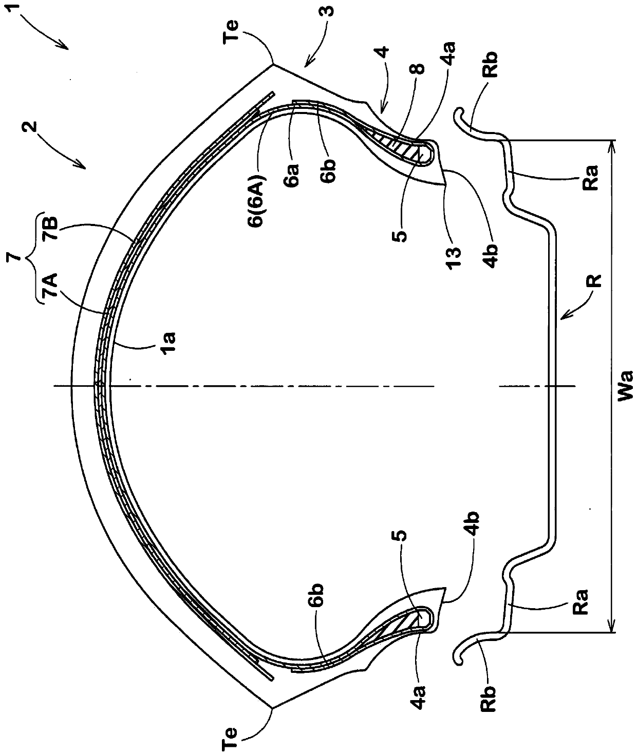
[0021] figure 1 It is a tire meridian cross-sectional view showing a tire rotation axis (not shown) in a pre-assembled state of a pneumatic tire (hereinafter, sometimes simply referred to as a "tire") 1 according to an embodiment of the present invention. In this embodiment, a motorcycle tire is shown as a preferable tire 1 . In addition, the tire 1 of the present invention is not limited to motorcycle tires.

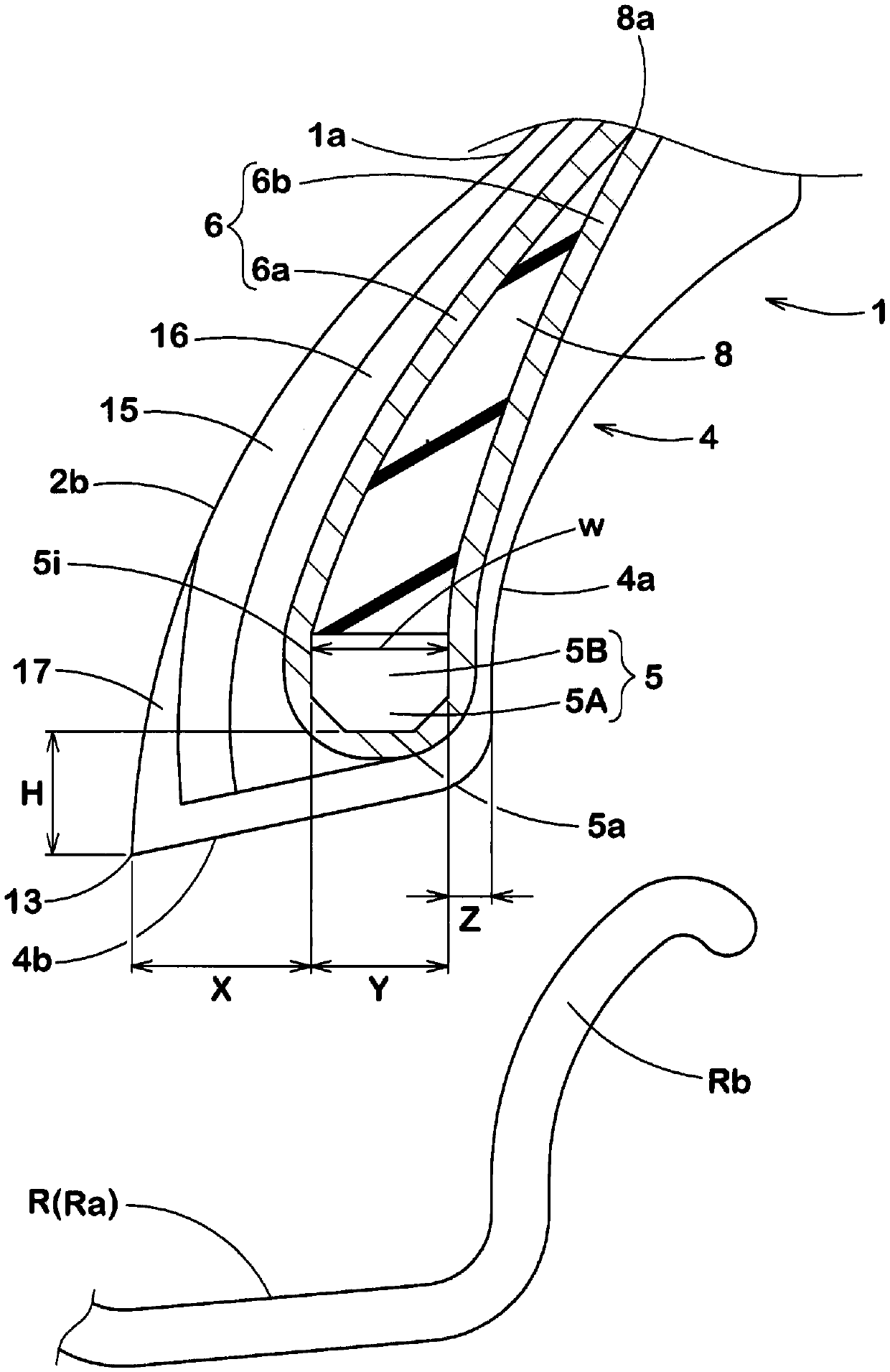
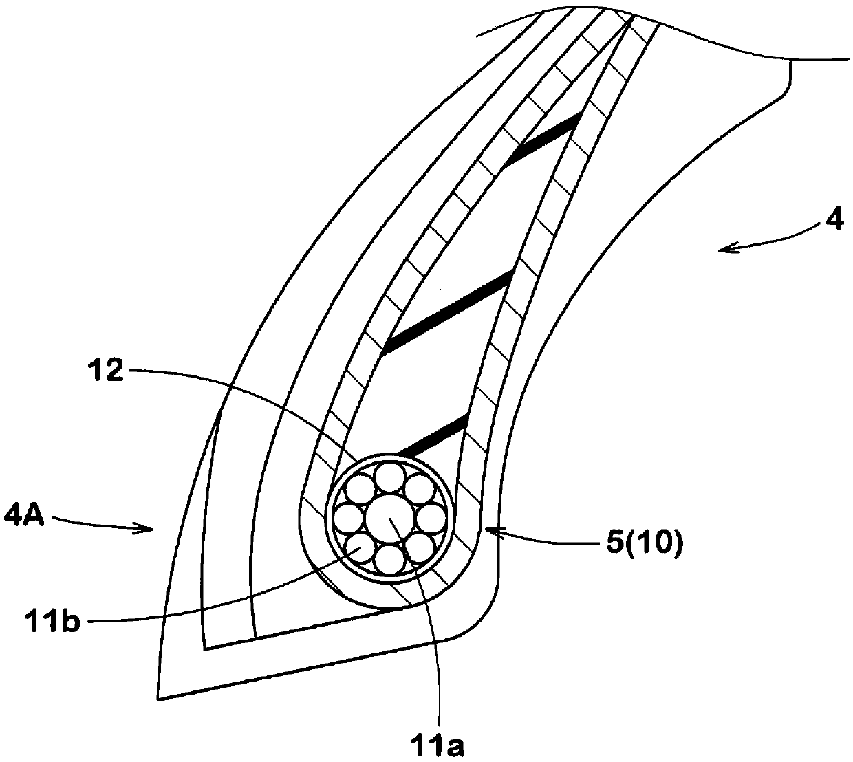
[0022] The tire 1 of the present embodiment has a carcass 6 extending from the tread portion 2 to the bead core 5 of the bead portion 4 via the sidewall portion 3 , and a belt layer 7 disposed outside the carcass 6 in the radial direction of the tire. .

[0023] The carcass 6 is formed of at least one layer (in this embodiment, one layer) of carcass ply 6A. The carcass ply 6A includes: a main body portion 6a annularly spanned between a pair of bead cores 5, 5; and ...


PUM


Abstract

The invention provides a pneumatic tire, capable of improving mosaic property with a rim and operation stability in a balanced manner. A pneumatic tire 1 comprises bead portions 4 each having a bead core 5 therein. Each of the bead portions 4 has an outer side surface (4a) which is to be in contact with a standard rim (R) on an outer side in a tire axial direction of the bead core 5. In a tire meridian section of the pneumatic tire in a premounted state, a distance (H) in a tire radial direction between an inner end (5a) in a tire radial direction of the bead core 5 and a bead toe 13 is largerthan 0.5 times and smaller 2.5 times a maximum width (Y) in the tire axial direction of the bead core 5.

Description

technical field [0001] The present invention relates to a pneumatic tire having a bead core. Background technique [0002] Conventionally, in a pneumatic tire, for example, the bead portion is displaced from the rim in the tire axial direction due to a large lateral force acting when turning, for example, and the steering stability performance is deteriorated. In order to suppress such rim misalignment, for example, it is conceivable to increase the adhesion between the rim and the bead portion by increasing the fastening force to the rim. [0003] However, such a pneumatic tire has a problem that it is difficult to fit the bead portion to the rim, and the fitting performance with the rim tends to deteriorate. In addition, Patent Document 1 described below describes a technique for improving fitability with a rim. [0004] Patent Document 1: Japanese Patent No. 4926314 Contents of the invention [0005] The present invention has been made in view of the above circumstan...

Claims


Application Information

Patent Timeline
Patent Type & Authority Applications(China)
IPC IPC(8): B60C9/02
CPCB60C2200/10B60C15/00B60C15/04B60C15/024B60C2015/0245B60C2015/0614
Inventor 梶田久贵
Owner SUMITOMO RUBBER IND LTD
Learn More