Laser pulse energy adjusting device and method and multi-level pulse laser
A technology of laser pulse and energy adjustment, which is applied in the direction of measuring devices, instruments, radio wave measuring systems, etc., can solve the problems of complex circuits in the subsequent stage, different group delays, and affecting timing accuracy, etc., and achieve simple overall structure and high distance measurement The effect of precision
- Summary
- Abstract
- Description
- Claims
- Application Information
AI Technical Summary
Problems solved by technology
Method used
Image

Examples
Embodiment 1
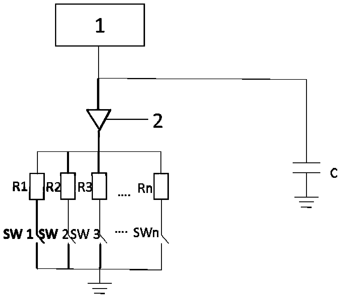
[0068] Such as figure 1 As shown, the multi-level pulsed laser in this embodiment includes a laser power supply 1, a laser 2, an energy storage capacitor C for driving the laser, and a laser pulse emission control module; an energy storage capacitor C for driving the laser, a laser power supply 1 and a laser 2 The negative electrode of the laser device 2 is connected to the laser pulse emission control module; in this embodiment, the laser pulse emission control module includes N-level parallel discharge resistors with different resistance values. The N-level discharge control switch is connected.
[0069] In the laser pulse emission circuit, the energy storage capacitor C for driving the laser is fixed, and the multi-level driving pulse for driving the laser is generated by means of multi-level discharge resistors. For example, using N-level discharge resistors, that is, using N discharge resistors with different resistance values to arrange and combine can produce 2 N -1...
Embodiment 2
[0077] Such as Figure 5 As shown, the multi-level pulsed laser in this embodiment includes a laser power supply 1, a laser 2, a discharge resistor R for driving the laser, and a laser pulse emission control module; the discharge resistor R for driving the laser is connected to the laser, and one end of the laser pulse emission control module Connect with the laser cathode and laser power supply 1, and the other end is grounded. The laser pulse emission control module of this embodiment includes N parallel energy storage capacitors with different capacitances, one end of the N energy storage capacitors is connected to the laser power supply and the laser, and the other end is respectively connected to N control switches; it also includes a main The control switch SW0 is connected with the laser and is used to control the on-off of the current passing through the laser.
[0078] In the laser pulse emission circuit, the discharge resistance of the laser is fixed, and the multi-...
Embodiment 3
[0084] Such as Figure 6 As shown, the multi-level pulsed laser in this embodiment includes a laser power supply 1, a laser 2, an energy storage capacitor C for driving the laser, and a laser pulse emission control module; an energy storage capacitor C for driving the laser, a laser power supply 1 and a laser 2 The negative electrode of the laser device 2 is connected to the laser pulse emission control module; in this embodiment, the laser pulse emission control module includes a main circuit resistor R0; N-level parallel discharge resistors with different resistance values, and one end of the N-level discharge resistance is connected in parallel with the laser , and the other ends are respectively connected to N-level discharge control switches.
[0085] In the laser pulse emission circuit, the energy storage capacitor C for driving the laser is fixed, and the multi-level driving pulse for driving the laser is generated by means of multi-level discharge resistors. For examp...
PUM
 Abstract
Description
Claims
Application Information
 - Generate Ideas
- Intellectual Property
- Life Sciences
- Materials
- Tech Scout
- Unparalleled Data Quality
- Higher Quality Content
- 60% Fewer Hallucinations
Browse by: Latest US Patents, China's latest patents, Technical Efficacy Thesaurus, Application Domain, Technology Topic, Popular Technical Reports.
© 2025 PatSnap. All rights reserved.Legal|Privacy policy|Modern Slavery Act Transparency Statement|Sitemap|About US| Contact US: help@patsnap.com