
Wind-resistant locking device for final closure of steel truss beams erected by hole and application method thereof

A locking device, a technology of steel truss, applied in the erection/assembly of bridges, truss bridges, bridge construction, etc., can solve the problems of weak wind resistance, poor stability, damage to steel truss girder down the river wharf and large floating cranes, etc. To achieve the effect of simple structure, safe and efficient method, convenient and quick use

Active Publication Date: 2019-06-11
CHINA RAILWAY MAJOR BRIDGE ENG GRP CO LTD
View PDF12 Cites 1 Cited by
  • Summary
  • Abstract
  • Description
  • Claims
  • Application Information

AI Technical Summary

Problems solved by technology

[0003] However, from March to October every year, unforeseen hurricanes or squall line winds frequently occur in the bridge site area. The highest wind speed in 10 years during the steel truss erection stage reaches 39.25m / s. On the one hand, the super strong squall line The wind has damaged the steel truss girder down the river wharf and the large floating crane; on the other hand, when the steel truss girder to be erected and the steel truss girder that has been erected are combined and docked, the wind resistance and stability of the two are weak. Closed docking security is low

Method used


Image

  • Wind-resistant locking device for final closure of steel truss beams erected by hole and application method thereof
  • Wind-resistant locking device for final closure of steel truss beams erected by hole and application method thereof

Examples


Embodiment Construction

[0034] The present invention will be described in further detail below in conjunction with the accompanying drawings and embodiments.

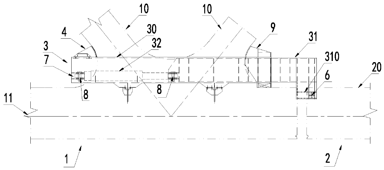
[0035] see figure 1 with figure 2 As shown, the embodiment of the present invention provides a wind-resistant locking device for erecting a steel truss girder hole by hole, which is used to temporarily lock the erected A-span steel truss girder 1 and the B-span steel truss girder 2 to be erected , the wind-resistant locking device includes two telescopic arms 3, a rear beam 4 and two push mechanisms 6;

[0036] combine figure 1 with figure 2 As shown, two telescopic arms 3 are respectively arranged on both sides of the oblique rod 10 of the A-span steel truss girder 1 along the transverse bridge direction, and the telescopic arms 3 include an outer sleeve 30 , an inner sleeve 31 and a driving mechanism 32 .

[0037] The outer sleeve 30 in this embodiment is U-shaped, and the U-shaped single limb is a box-shaped structure, which is welded...


PUM


Abstract

The invention discloses a wind-resistant locking device for a final closure of steel truss beams erected by hole and an method. The wind-resistant locking device is used for temporarily locking an erected A span steel truss beam and a B span steel truss beam to be erected and comprises two telescopic arms, a rear cross beam and two pushing mechanisms, wherein the two telescopic arms are respectively arranged on the two sides of a diagonal member of the A span steel truss beam along a transverse direction of bridge, and each telescopic arm comprises an outer sleeve, an inner sleeve and a driving mechanism; the outer sleeve is arranged on an A span lower chord member of the A span steel truss beam, and the inner sleeve is partly positioned in the outer sleeve; the driving mechanism is arranged in the outer sleeve, is connected with the inner sleeve and is used for driving the inner sleeve to move along a longitudinal direction of bridge; the rear cross beam is connected with the two outer sleeves; a containing area used for containing a B span lower chord member of the B span steel truss beam is formed between the inner sleeves of the two telescopic arms; and one ends of the two pushing mechanisms are respectively fixed onto the two inner sleeves and are positioned outside the outer sleeves, and the other ends of the two pushing mechanisms can extend or retract towards the containing area along the transverse direction of bridge. The wind-resistant locking device can improve the overall wind resistance during erection of the steel truss beams.

Description

technical field [0001] The invention relates to the technical field of bridge engineering superstructure steel truss girder hole-by-hole erection, in particular to a steel truss girder hole-by-hole erection closure wind-resistant locking device and a method of use. Background technique [0002] In the construction of the superstructure of the existing bridge engineering, the general multi-span and multi-connected long-span steel truss girders are erected hole by hole as follows: after the long-span steel truss girders are moved longitudinally and laterally to the steel truss girders at the wharf, Transported to the hole to be erected, the first-span steel truss girders in the first-span are directly erected by large-scale floating cranes, and the steel truss girders of the other spans except the first span are installed hole by hole with the assistance of diamond-shaped steel girder hangers until the first-span steel trusses are erected beam. [0003] However, from March to...

Claims


Application Information

Patent Timeline
IPC IPC(8): E01D21/00E01D6/00E01D101/30
Inventor 徐平安毛伟琦涂满明卢鹏黄晓剑李方峰刘建华潘军余本俊孙刘洋
Owner CHINA RAILWAY MAJOR BRIDGE ENG GRP CO LTD
Learn More