
Aluminum attachment method and vacuum conveying cavity structure of metallic thin film coating machine

A metal thin film, vacuum conveying technology, applied in metal material coating process, vacuum evaporation plating, coating and other directions, can solve the problems of increasing equipment manufacturing cost, spending a lot of time, low work efficiency, etc., to shorten the transportation distance, The effect of saving production costs and reducing production costs

Inactive Publication Date: 2019-06-11
SKYTECH
View PDF6 Cites 0 Cited by
  • Summary
  • Abstract
  • Description
  • Claims
  • Application Information

AI Technical Summary

Problems solved by technology

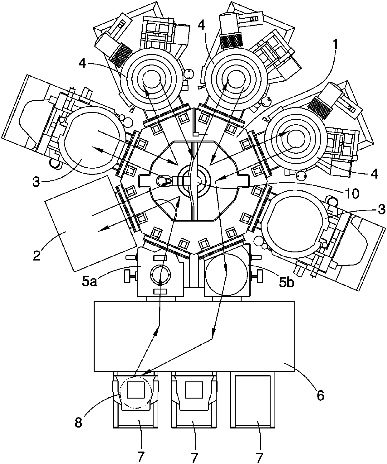
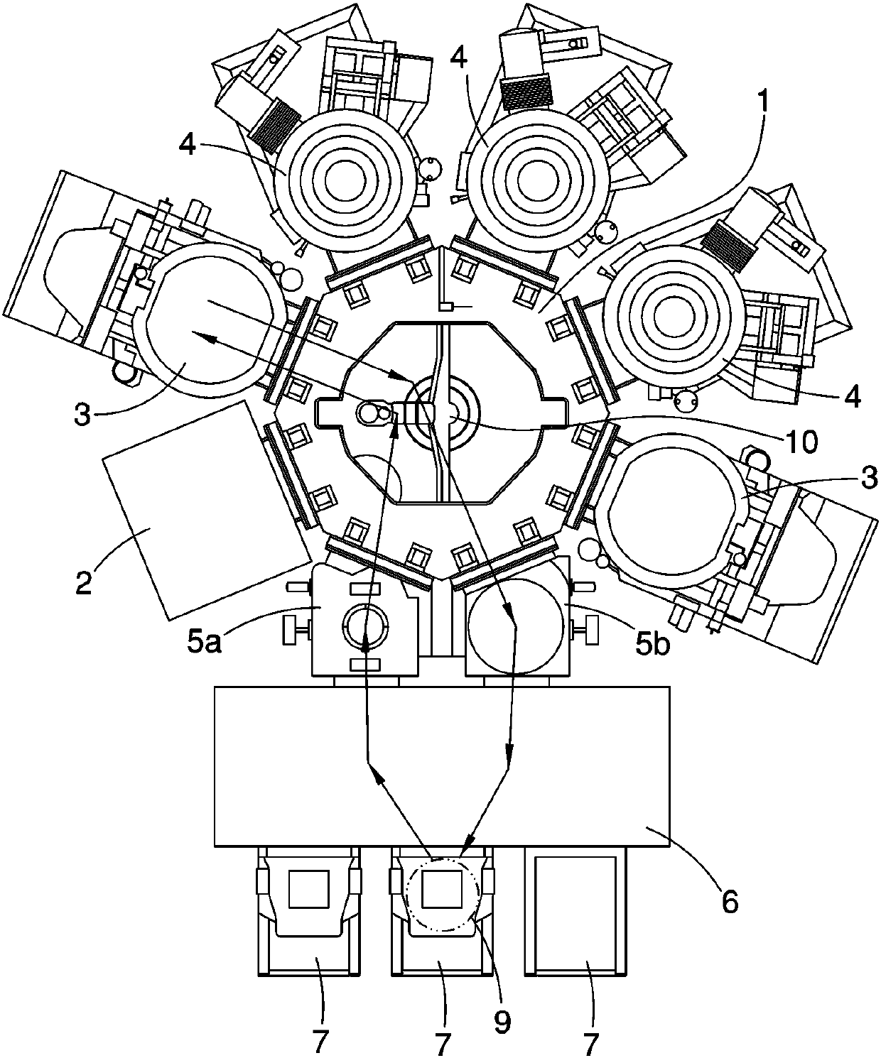
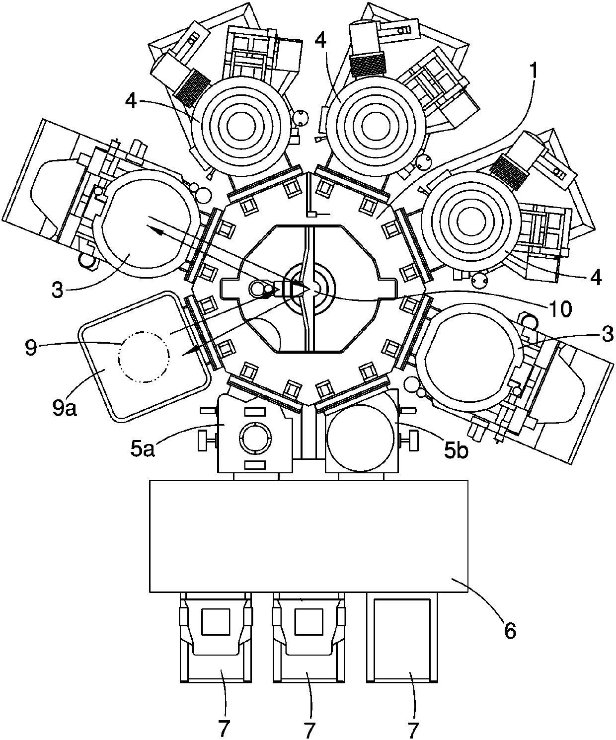
[0008] The main purpose of the present invention is to solve the problem that the aluminum attachment method of the known metal thin film coating machine needs to spend a lot of time on repeated vacuuming and back pressure operations, so that the work efficiency is very low, and the space of the vacuum transfer chamber will be occupied. One opening position will affect other processes, and will greatly increase equipment manufacturing costs and many other problems, and provide an aluminum attachment method and a vacuum transfer chamber structure for a metal thin film coating machine

Method used


Image

  • Aluminum attachment method and vacuum conveying cavity structure of metallic thin film coating machine
  • Aluminum attachment method and vacuum conveying cavity structure of metallic thin film coating machine
  • Aluminum attachment method and vacuum conveying cavity structure of metallic thin film coating machine

Examples


Embodiment Construction

[0042] see Figure 4 , Figure 5 As shown, the aluminum attachment method of the metal thin film coating machine according to the present invention is shown. Wherein, the metal thin film coating machine includes a vacuum transfer chamber 1 and a pre-etching reaction chamber 3 which is connected to the periphery of the vacuum transfer chamber 1 and is in a high vacuum state. arm 10. The aluminum attachment method includes:

[0043] (a) At least one placement rack 11 is provided at a position where the vacuum transfer chamber 1 does not affect the transfer of the wafer 8 by the robot arm 10, and the placement rack 11 can store an aluminum sheet 9;

[0044] (b) Utilize the mechanical arm 10 to remove the aluminum sheet 9 from the placement rack 11, and send it to the pre-etching reaction chamber 3;

[0045] (c) bombarding the aluminum sheet 9 with plasma in the pre-etching reaction chamber 3, so that the aluminum on the aluminum sheet 9 is plated on the inner wall of the pre-...


PUM


Abstract

The invention provides an aluminum attachment method and a vacuum conveying cavity structure of a metallic thin film coating machine. The aluminum attachment method and the vacuum conveying cavity structure are mainly characterized in that at least one placement frame is arranged at a position, which does not influence the process of conveying wafers through a mechanical arm, in a vacuum conveyingcavity of the metallic thin film coating machine, and is used for storing an aluminum sheet; then the aluminum sheet is placed between the placement frame and a prepositioned reaction chamber throughthe mechanical arm and then is conveyed, and then an aluminum attachment manufacture procedure is carried out; and the structure provided by the invention has the effects of improving the working efficiency and reducing the manufacture cost of equipment.

Description

technical field [0001] The present invention relates to a semiconductor bump manufacturing process and equipment for the manufacturing process, especially a metal thin film coating machine that can effectively use the space of the vacuum transfer chamber to greatly improve the work efficiency of the aluminum attachment process and reduce the manufacturing cost of the equipment Aluminum attachment method and vacuum transfer cavity structure. Background technique [0002] In order to meet the "short, small, light, and thin" requirements of portable high-performance microelectronic products, the traditional wire bonding (Wire Bonding) as the electronic packaging technology for bonding chips to various substrates has long been insufficient for application requirements. Instead, the flip-chip bonding technology that uses bumps instead of gold wires as the chip and substrate bonding is the key core technology of wafer-level packaging. In the semiconductor bump manufacturing proce...

Claims


Application Information

Patent Timeline
Patent Type & Authority Applications(China)
IPC IPC(8): C23C14/02C23C14/56C23C16/02
Inventor 李承峯詹伟良马国洋易锦良黄裕鸿
Owner SKYTECH
Learn More