
Cone-shaped screw

A tapered screw, tapered rod technology, applied to the tapered screw. It can solve the problems of high cost, slow rising speed of extrusion force, unsatisfactory material processing effect, etc., and achieve the effect of accelerating deformation and flow, improving efficiency and increasing the number of mixing times

Inactive Publication Date: 2019-06-11
浙江光明塑料机械有限公司
View PDF1 Cites 0 Cited by
  • Summary
  • Abstract
  • Description
  • Claims
  • Application Information

AI Technical Summary

Problems solved by technology

However, the pitch of the extrusion screw feed section is relatively wide, the extrusion force on the material rises slowly, it is difficult for the material to enter the molten state quickly, and the processing effect of the material is not ideal. In order to improve the processing effect, the length of the screw needs to be increased. The cost is high, so the structure of the extrusion screw needs to be further improved

Method used


Image

  • Cone-shaped screw
  • Cone-shaped screw
  • Cone-shaped screw

Examples


Embodiment Construction

[0032] The present invention will be further described in detail below in conjunction with the accompanying drawings and embodiments.

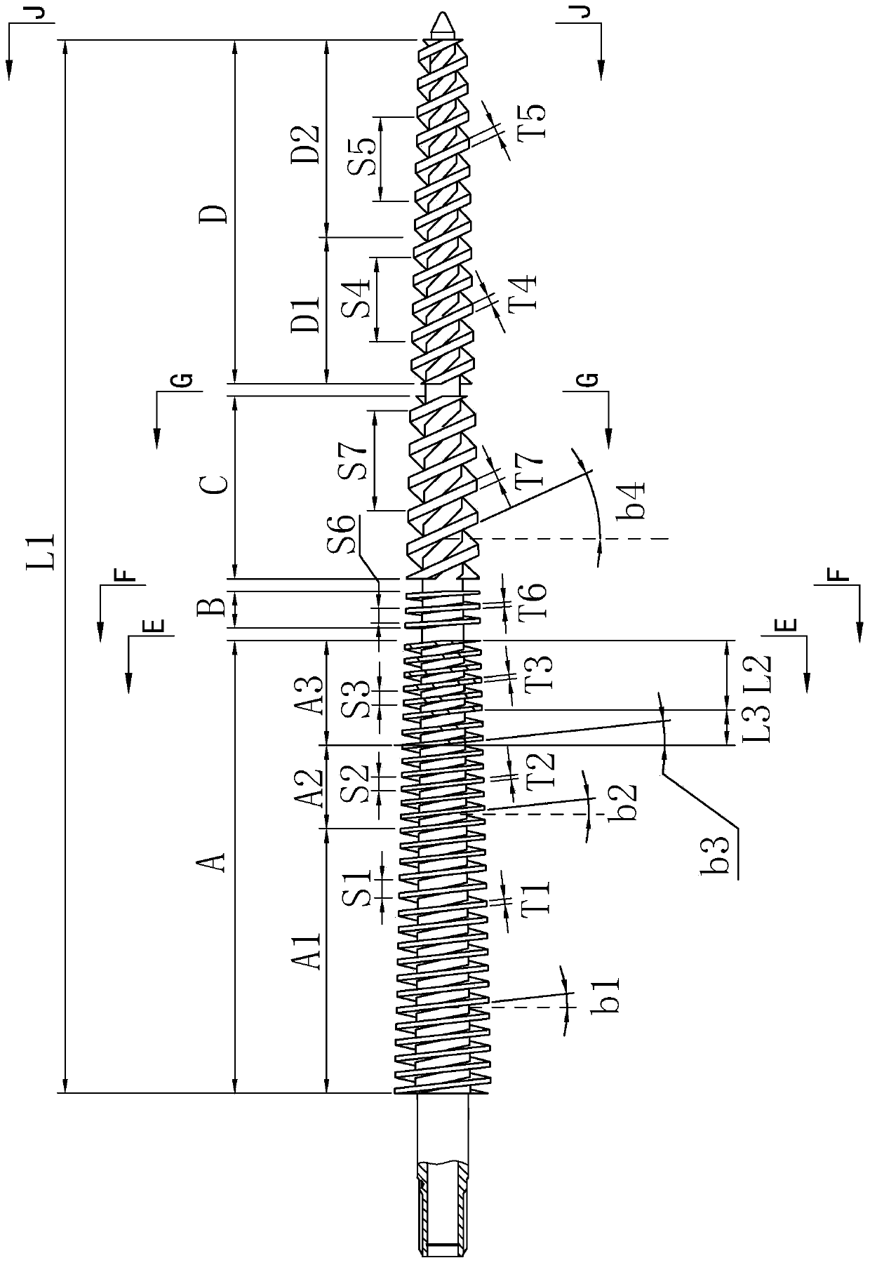
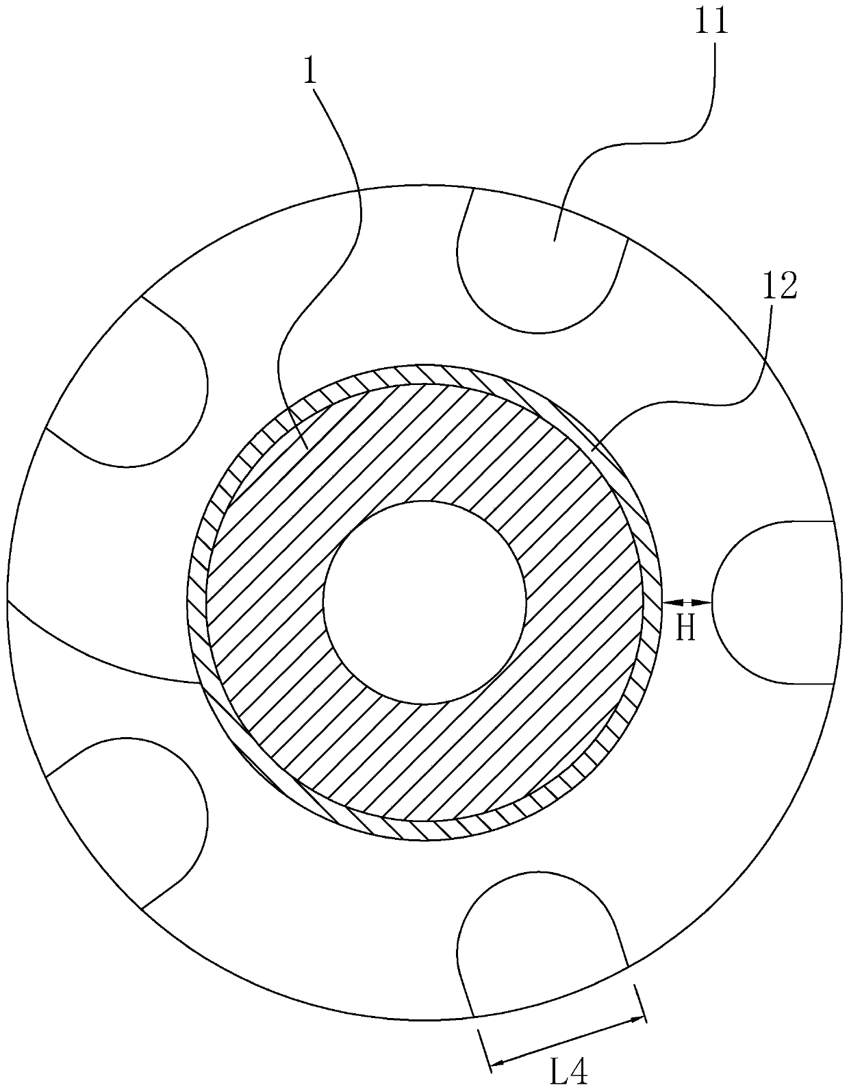
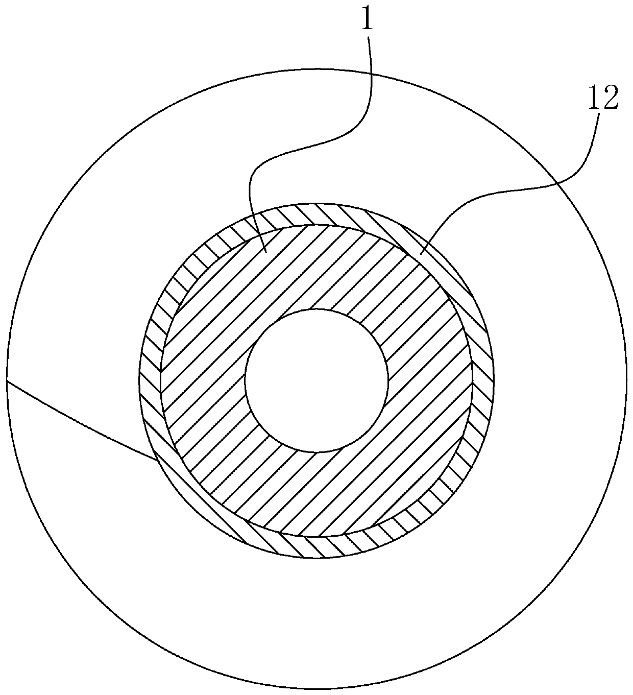
[0033] like Figure 1 to Figure 12 As shown, the conical screw of the present embodiment includes a tapered rod body 1 with a gradually reduced diameter and a screw flight arranged on the tapered rod body 1. The screw flight is divided into a feed section A, a melting section C, and a discharge section Section D, a transition section B is provided between the feed section A and the melting section C, the feed section A, the transition section B, the melting section C, and the helicoids of the discharge section D are arranged intermittently with each other, and the feed section The ratio of the length of A to the length L1 of the screw edge section on the tapered rod body 1 is 0.35 to 0.45. The feed section A is divided into the first section A1, the second section A2 and the third section A3, and the first section A1 , The screw flights of th...


PUM

PropertyMeasurementUnit
lengthaaaaaaaaaa
lengthaaaaaaaaaa
lengthaaaaaaaaaa

Abstract

The invention relates to a cone-shaped screw which comprises a cone-shaped rod body and a spiral edge. The spiral edge is divided into a feeding section, a transitional section, a melting section anda discharging section. The ratio of length of the feeding section and length of the spiral edge on the cone-shaped rod body is 0.35-0.45; the feeding section is divided into a first feeding section, asecond feeding section and a third feeding section; the spiral edges of the first feeding section, the second feeding section and the third feeding section are successively connected end to end, andthe separation distances between the spiral edges of the first feeding section, the second feeding section and the third feeding section are successively reduced; the separation distance between the spiral edges of the first feeding section is 21.5-25 mm, the separation distance between the spiral edges of the second feeding section is 18.5-21 mm, and the separation distance between the spiral edges of the third feeding section is 15-18 mm. The cone-shaped screw has the advantages that the separation distances between the spiral edges of the screw feeding section is far smaller than that in the prior art, and a material entering the feeding section can be extruded quickly, so that the material is melted more quickly; the spiral edges of the feeding section are good in continuity, so that smooth transition of the material in the feeding section is achieved.

Description

technical field [0001] The invention relates to the field of screw manufacturing, in particular to a tapered screw. Background technique [0002] There is an existing Chinese invention patent application with the application number CN201810683150.5 titled "A Kind of Extrusion Screw", which discloses an extrusion screw, which includes a tapered rod body with a gradually decreasing diameter and a screw flight arranged on the tapered rod body. , the screw flight is divided into a feeding section, a melting section, a homogenizing section and an extruding section, and it is characterized in that: a transition section is provided between the feeding section and the melting section, and a transition section is provided between the melting section and the homogenizing section , the screw flight pitch of the feed section, the transition section and the melting section decreases successively, the flight spacing of the second transition section is greater than or equal to the flight s...

Claims


Application Information

Patent Timeline
Patent Type & Authority Applications(China)
IPC IPC(8): B29C48/525B29C48/535C23C8/26
Inventor 包奇斌包明刚王明力殷武伟刘毅王科平胡泽民张麒麟陆峥军陈辉谢宏波
Owner 浙江光明塑料机械有限公司
Learn More