
Injection mould of locomotive toy series

A technology for injection molds and locomotives, which is applied in the field of injection molds for locomotive toy series. It can solve the problems of large equipment size, affecting the mold clamping of the upper and lower molds, and inconvenient use and replacement, and achieves the effects of high merging precision, energy saving, and convenient use.

Pending Publication Date: 2019-06-11
福建省靖虹模具科技有限公司
View PDF6 Cites 2 Cited by
  • Summary
  • Abstract
  • Description
  • Claims
  • Application Information

AI Technical Summary

Problems solved by technology

[0003] However, the water-cooling system in the upper and lower molds in the prior art needs to be installed with an external water-cooled water tank during use, resulting in a large volume of the entire equipment, and complicated water pipe connections, which will affect the clamping of the upper and lower molds, and when making unreasonable products, The mold needs to be replaced. At this time, the water supply system needs to be disassembled and then installed on the replaced mold, and the replaced mold must also be equipped with connectors, etc., which not only increases the cost of preparation, but also causes inconvenience in use and replacement.

Method used


Image

  • Injection mould of locomotive toy series
  • Injection mould of locomotive toy series
  • Injection mould of locomotive toy series

Examples


Embodiment 1

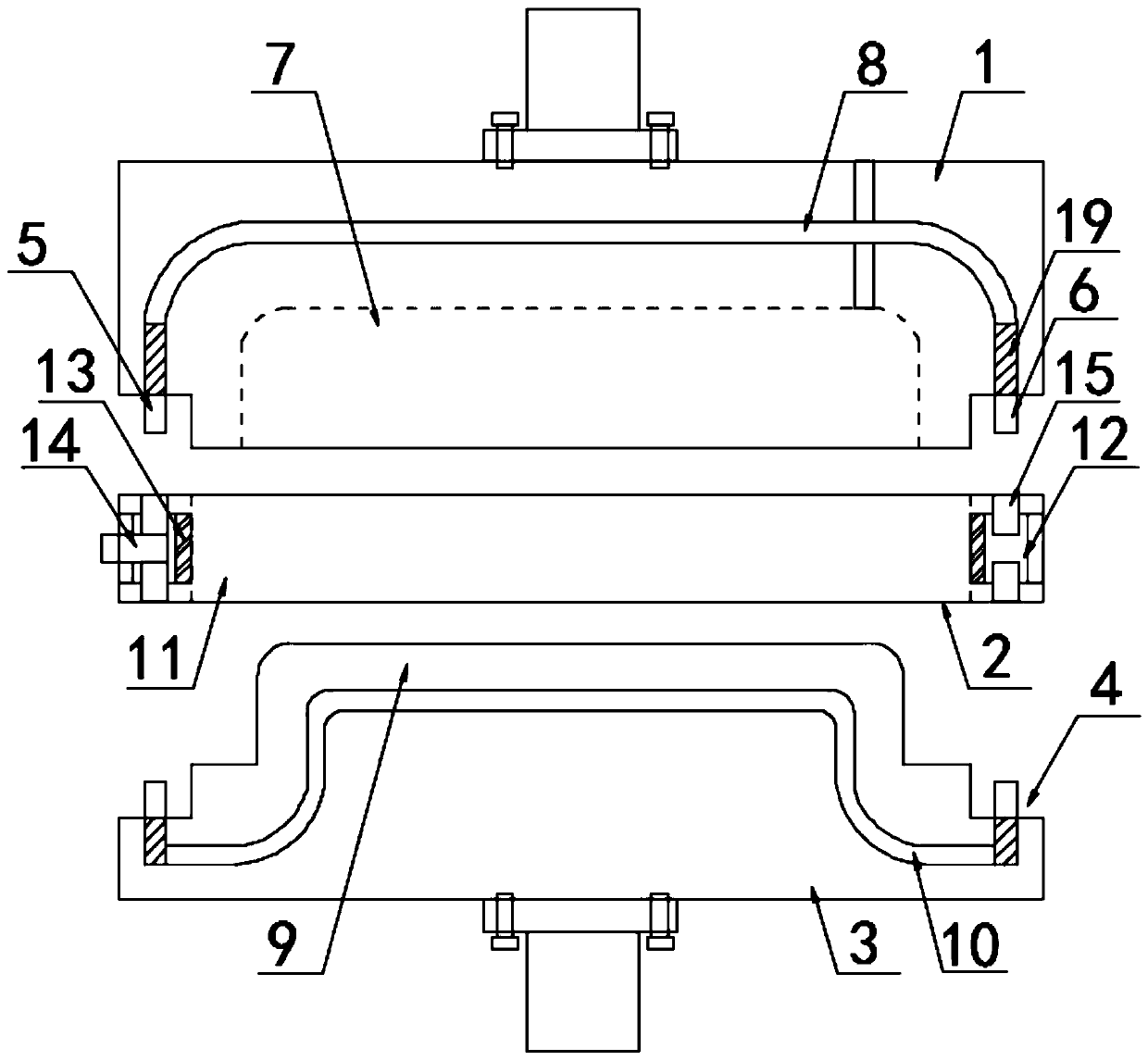
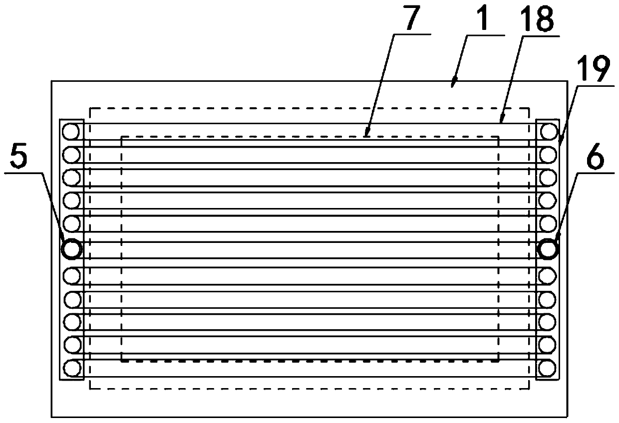
[0024] according to Figure 1-2 The injection mold of a locomotive toy series shown includes an upper mold 1, an intermediate cooling positioning frame 2 and a lower mold 3. The upper mold 1 and the lower mold 3 are respectively movably arranged on the top and bottom of the intermediate cooling positioning frame 2, so Both the bottom edge of the upper mold 1 and the top edge of the lower mold 3 are provided with a step 4, the step 4 is provided with a water inlet pipe 5 on one side and a water outlet pipe 6 on the other side, and the bottom surface of the upper mold 1 is provided with a mold groove 7. The upper mold 1 corresponding to the top of the mold cavity 7 is provided with an upper cooling system 8, the top of the lower mold 3 is integrally connected with a mold core 9, and the lower mold 3 corresponding to the bottom of the mold core 9 is provided with a lower mold 3 In the cooling system 10, a through groove 11 is provided on the inner side of the intermediate cooling p...

Embodiment 2

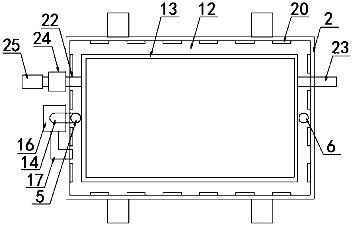
[0031] according to figure 2 In the injection mold of a locomotive toy series shown, the internal refrigeration channel 12 is arranged in a rectangular frame shape, and the inner and outer walls of the internal refrigeration channel 12 are provided with a semiconductor refrigeration fin 20. The inner and outer walls of the channel 12 are arranged in close contact, and the intermediate cooling positioning frame 2 is made of aluminum alloy material to facilitate the heat dissipation of the hot end of the semiconductor refrigeration fin 20;

[0032] according to figure 2 In the injection mold of a locomotive toy series shown, one side of the outer refrigeration channel 13 is provided with an air inlet pipe 22 and the other side is provided with an air outlet pipe 23. Both the air inlet pipe 22 and the air outlet pipe 23 penetrate the inner refrigeration channel 12 And the outer wall of the intermediate cooling positioning frame 2 and extending to the outside of the intermediate coo...


PUM


Abstract

The invention discloses an injection mould of locomotive toy series, and particularly relates to the field of toy injection moulds. The injection mould includes an upper mould, a middle cooling positioning frame and a lower mould, wherein the upper mould and the lower mould are correspondingly and movably arranged at the top and the bottom of the middle cooling positioning frame, steps are correspondingly arranged on the edge of the bottom of the upper mould and the edge of the top of the lower mould, a water inlet pipe is arranged on one sides of the steps, a water outlet pipe is arranged onthe other sides of the steps, and a mould groove is formed in the surface of the bottom of the upper mould. The injection mould of the locomotive toy series is arranged in the middle cooling positioning frame by using a cooling water circulating water supply system, in use, circulating water after cooling in an internal cooling passage is extracted and transported into the upper mould and the lower mould through a circulating pump, an injection molded part in the mould groove is cooled, the problem that in the prior art, water cooled systems need to be reconnected after the upper mould and thelower mould are replaced due to water cooled circulation systems internally arranged in the upper mould and the lower mould is solved, and the cost that the water cooled systems are both arranged ineach upper mould and each lower mould is also saved.

Description

Technical field [0001] The present invention relates to the technical field of toy injection molds, more specifically, the present invention relates to an injection mold of locomotive toy series. Background technique [0002] The injection molding process refers to the process of making a semi-finished part of a certain shape by pressing, injecting, cooling, and detaching molten raw materials; the existing locomotive toy series first inject the plastic melt through the injection hole during the injection molding process. After the injection is completed, it needs to be cooled by the water cooling system in the upper and lower molds to facilitate post-molding and demolding by the ejector rod. [0003] However, the water-cooling system in the upper and lower molds in the prior art requires an external water-cooled water tank when in use, resulting in a large volume of the entire equipment and complicated water pipe connection, which will affect the clamping of the upper and lower mol...

Claims


Application Information

Patent Timeline
IPC IPC(8): B29C45/26B29C45/73
Inventor 钱建根王炜杰
Owner 福建省靖虹模具科技有限公司
Learn More