Auxiliary switch of switch device

A switch device and auxiliary switch technology, which is applied to the power device, electric switch, and electrical components inside the switch. It can solve the problems of auxiliary head burning, damage to the life of auxiliary contacts, and slow arc extinguishing speed to ensure contact. Reliability, quick breaking of the arc, and the effect of extending the life of the contacts

Pending Publication Date: 2019-06-07
CHANGSHU SWITCHGEAR MFG CO LTD (FORMER CHANGSHU SWITCHGEAR PLANT)
View PDF0 Cites 0 Cited by
  • Summary
  • Abstract
  • Description
  • Claims
  • Application Information

AI Technical Summary

Problems solved by technology

In this case, the auxiliary switch driven by the main shaft will also produce reciprocating motion of the auxiliary contact, which will cause the auxiliary contact to make multiple contacts, which will seriously affect the life of the auxiliary contact of the auxiliary switch, resulting in the use of auxiliary switches. Counting errors or using auxiliary switches to collect closing and opening state errors
In addition, due to the large mass of the main contact of the circuit breaker, the acceleration is relatively small, and the acceleration for driving the auxiliary switch is correspondingly small. Therefore, the slow acceleration of the main contact makes the auxiliary contact of the auxiliary switch slow in breaking speed, which is not conducive to rapid extinguishing. arc, and the slow arc extinguishing speed will damage the life of the auxiliary contact, and even cause the auxiliary head to burn out (ablation) due to the inability to break the arc under high DC voltage

Method used


Image

  • Auxiliary switch of switch device
  • Auxiliary switch of switch device
  • Auxiliary switch of switch device

Examples


Embodiment 1

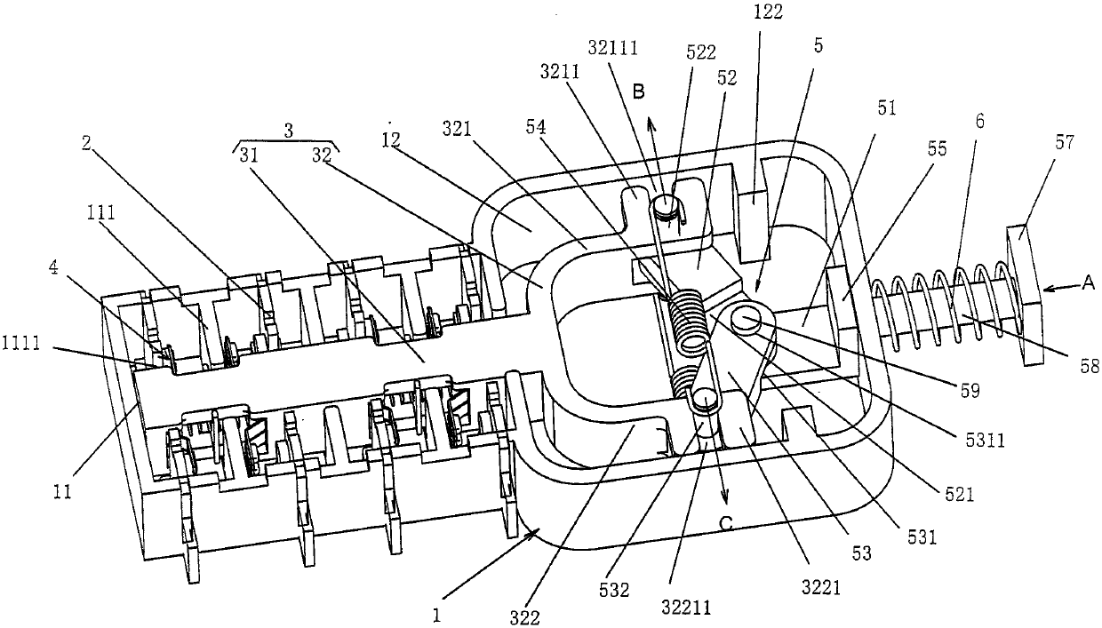
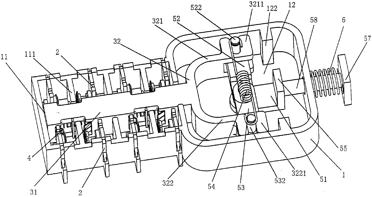
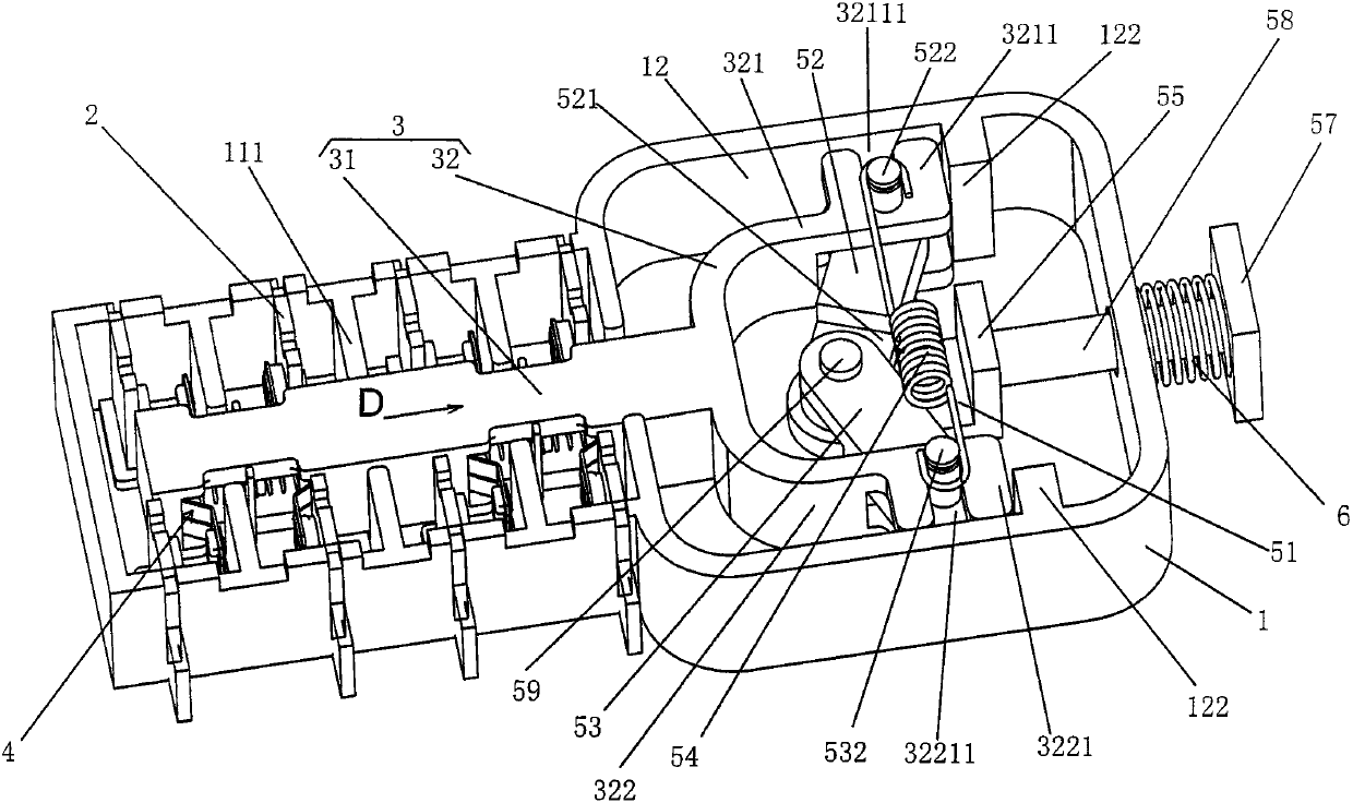
[0038] See Figure 1 to Figure 3 , showing the housing 1 of the structure system of the auxiliary switch of the switching device of the present invention, the contact system and the transmission device arranged in the housing 1, the aforementioned switching device has a first state and a second state and in the first state and the second state, the aforementioned transmission device accepts (also called "receive") the action of the switching device and actuates the aforementioned contact system to move between the first position and the second position, and the contact The system reflects a first state of the switchgear when in the first position, and the contact system reflects a second state of the switchgear when in the second position.

[0039] The switchgear of the present invention has the main contact of the main circuit, which drives the separation and closure of the dynamic and static contacts of the main contact through the rotation of the main shaft. The separation ...

Embodiment 2

[0055] See Figures 10 to 16 , relative to Embodiment 1, this Embodiment 2 shows another structure of the spring driving device 5 .

[0056]As described in Embodiment 1, the aforementioned U-shaped rod body 32 has a first arm 321 and a second arm 322, and the spring driving device 5 in Embodiment 2 includes a central link 51, first and second compression springs 511, 512 and the return spring sleeve rod 58, the central link 51, the first compression spring 511 and the second compression spring 512 are arranged in the aforesaid drive device accommodation chamber 12, and the first compression spring 511 and the second compression spring 512 are arranged symmetrically to each other. One end of the first compression spring 511 is supported on the first compression spring support head 513, and the other end of the first compression spring 511 is supported on the second compression spring support head 514, and one end of the second compression spring 512 is supported on the third pr...


PUM


Abstract

An auxiliary switch of a switch device includes a housing, and a contact system and a transmission device disposed in the housing, wherein the switch device has first and second states. The transmission device includes a return spring, a guide rod and a spring drive device, the guide rod is arranged in the housing, a spring driving device is disposed in the housing and connected to the guide rod,the return spring is disposed on the spring driving device, when the switch device is operated from the first state to the second state, the spring driving device is driven for energy storage and is driven to cross a dead center position to release energy to drive motion of the guide rod, and the guide rod drives the contact system to move from the first position to the second position; and when the switch device is operated from the second state to the first state, the return spring drives the spring driving device for energy storage, the spring driving device is driven to cross the dead center position to release energy to drive motion of the guide rod, and the guide rod drives the contact system to move from the second position to the first position. The auxiliary switch of the switch device facilitates rapid switching-off of arc, prolongs the contact life and improves the contact reliability.

Description

technical field [0001] The invention belongs to the technical field of low-voltage electrical appliances, and in particular relates to an auxiliary switch of a switching device. Background technique [0002] Switching devices such as frame circuit breakers, molded case circuit breakers and contactors are usually equipped with auxiliary switches, which reflect the opening and closing status of the switching devices. The auxiliary switch includes a housing, a contact system arranged in the housing, and a transmission device for receiving (that is, accepting) the action of the switch device to actuate the action of the contact system. [0003] As known in the industry, the aforementioned frame circuit breaker has the function of closing and opening states and can switch between closing and opening states. Driven by the drive shaft, the aforementioned contact system can be switched between the disengaged position and the closed position, so as to reflect the opening and closing...

Claims


Application Information

Patent Timeline
IPC IPC(8): H01H3/30H01H9/38
Inventor 毛振风陈英朱冬明
Owner CHANGSHU SWITCHGEAR MFG CO LTD (FORMER CHANGSHU SWITCHGEAR PLANT)
Why Eureka
Try Eureka