
Non-concentric elastic compensation sealing assembly

A technology of elastic compensation and sealing components, which is applied in the direction of engine sealing, conveyor objects, engine components, etc., can solve the problems of poor non-contact sealing effect, affecting sealing and operation effect, reducing sealing performance, etc., and achieves low cost , Reliable axial compensation, convenient installation and removal

Pending Publication Date: 2019-06-07
山东太极龙塑胶科技有限公司 +1
View PDF2 Cites 0 Cited by
  • Summary
  • Abstract
  • Description
  • Claims
  • Application Information

AI Technical Summary

Problems solved by technology

[0005] The technical problem solved by this patent is that the non-contact sealing effect is not good, while the contact sealing is affected by the concentricity and the sealing and operation effect, and the sealing performance cannot be compensated after wear and tear, and the innovative design is carried out. The contact seal is not affected by the change of concentricity within a certain range. It can compensate and maintain the sealing pressure after wear and tear. The rotation resistance is small, and the non-concentric elastic compensation sealing assembly can be easily replaced and repaired.

Method used


Image

  • Non-concentric elastic compensation sealing assembly
  • Non-concentric elastic compensation sealing assembly
  • Non-concentric elastic compensation sealing assembly

Examples


Embodiment Construction

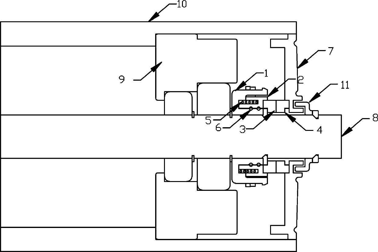
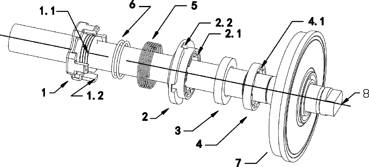
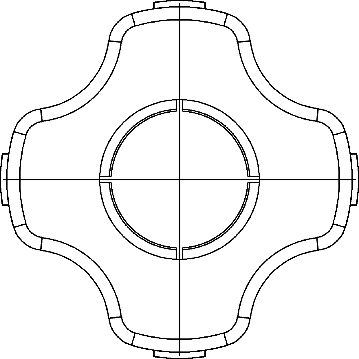
[0042] Such as figure 1 As shown, install the bearing chambers 9 at both ends of the idler cylinder 10, and then follow the figure 2 In the sequence shown, the static sleeve 1 is tightly fitted and pressed into the shaft 8, positioned and fixed on the outside of the bearing chamber 9, and will not move axially and rotationally, as shown in Figure 3-5 The shown static sleeve 1 is designed with a sealing ring groove 1.1 and elastic elastic teeth 1.2, and the sealing ring 6 is tightly fitted into the sealing ring groove 1.1 on the static sleeve 1 without moving, and the spring 5 is inserted into the static sleeve 1 on the inner side of the elastic teeth 1.2, such as Figure 6-8 The moving sleeve 2 shown is designed with an anti-rotation groove 2.1 and an elastic tooth hole 2.2. Insert the elastic tooth hole 2.2 on the moving sleeve 2 into the elastic tooth 1.2 on the static sleeve 1, and the anti-rotation groove 2.2 on the elastic tooth 1.2 The tooth removal has a certain deg...


PUM


Abstract

The invention discloses a non-concentric elastic compensation sealing assembly. The non-concentric elastic compensation sealing assembly is characterized by comprising a rotary motion assembly and anaxial motion assembly, wherein the rotary motion assembly and the axial motion assembly sleeve a shaft, the axial motion assembly comprises a static sleeve fixedly installed with the shaft, the staticsleeve is provided with a movable sleeve capable of axially moving, and the movable sleeve is fixedly provided with a wear-resistant static ring; and the rotary motion assembly comprises an outer cover rotationally mounted on the shaft, a wear-resistant movable ring is fixedly arranged on the outer cover, and the wear-resistant static ring and the wear-resistant movable ring are matched and sealed. The static sleeve is provided with elastic teeth, and the static sleeve I penetrates through elastic tooth holes of the movable sleeve to be limited through the elastic teeth. The movable sleeve isinternally provided with an anti-rotation groove with a concave-convex structure, the wear-resistant static ring is provided with a wear-resistant static ring groove matched with the anti-rotation groove, the wear-resistant movable ring I is provided with a wear-resistant movable ring groove with a concave-convex structure, and the wear-resistant movable ring groove and an outer cover groove of the outer cover which has the corresponding convex-concave structure are matched and fixed.

Description

technical field [0001] This patented technology is applicable to the non-concentric elastic compensation sealing assembly on the idler rollers or drums of belt conveyors used in industries such as industrial mining, ports, wharves, grain, steel mills, etc., to prevent bearings from being affected by water or dust and reduce their service life. Background technique [0002] Idler rollers and drums are the key components to ensure the normal operation of the belt conveyor. The seals in the idler rollers and drums are the key components that affect their normal operation. The bearing in the drum fails, increases the load of the belt conveyor, or wears out the cylinder and causes the belt to wear out or tear and other major accidents. [0003] At present, the seal in the roller or drum mainly adopts non-contact labyrinth seal, and a small amount of contact seal is also used. Both of these two seals have certain shortcomings. The non-contact seal is generally waterproof but not ...

Claims


Application Information

Patent Timeline
IPC IPC(8): F16J15/34B65G39/09
Inventor 朱玉兰刘明
Owner 山东太极龙塑胶科技有限公司
Learn More