In situ fenestration instrument

A fenestration and device technology, applied in the field of medical devices, can solve the problems of easy displacement, damage to surrounding blood vessels, and high risk, and achieve the effects of improving the accuracy of puncture, saving operation time, and widening the scope of application.

Pending Publication Date: 2019-06-07
HANGZHOU WEIQIANG MEDICAL TECH CO LTD
View PDF0 Cites 7 Cited by
  • Summary
  • Abstract
  • Description
  • Claims
  • Application Information

AI Technical Summary

Problems solved by technology

The problem with this technology is that the puncture needle cannot accurately find the central position of the opening of the branch blood vessel in the dynamic blood vessel, and it is easy to puncture or damage the surrounding blood vessels
Therefore, when this in situ fenestration device with an anchored balloon is used for antegrade fenestration, the balloon is located in the main blood vessel after expansion, which will block the blood flow of the main blood vessel, resulting in ischemia of the patient's entire lower extremity , the risk is extremely high; and the balloon is easily displaced under the high-speed impact of the aortic blood flow, which cannot guarantee the smooth and accurate puncture of the puncture needle
Therefore, this in situ fenestration device with an anchoring balloon can only cooperate with the bypass tube to achieve retrograde in situ fenestration, that is, the fenestration from branch vessels to the main vessel, but it cannot be used for antegrade in situ fenestration. window

Method used


Image

  • In situ fenestration instrument
  • In situ fenestration instrument
  • In situ fenestration instrument

Examples


Embodiment 1

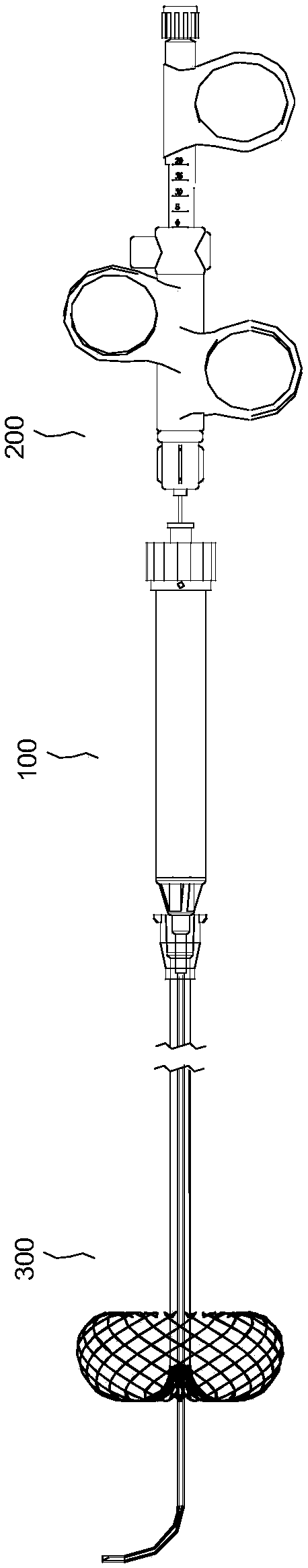
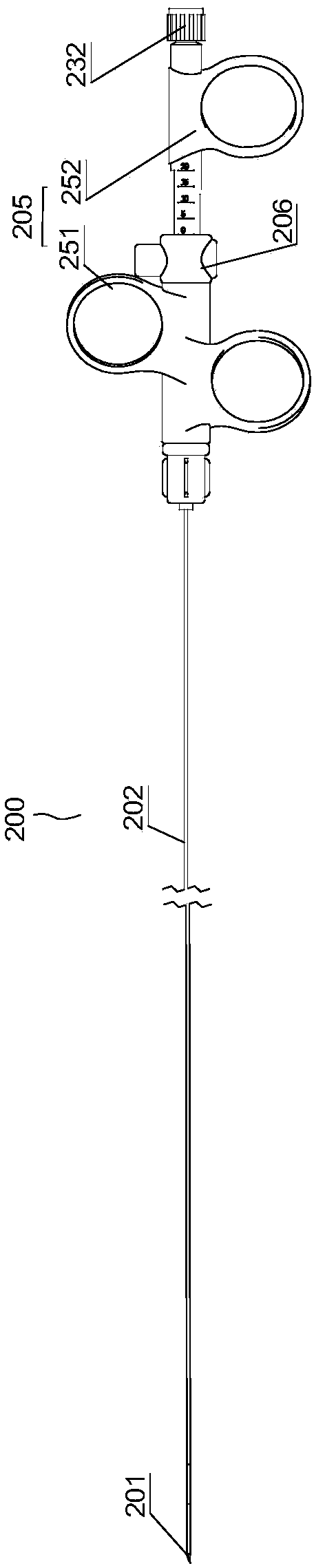
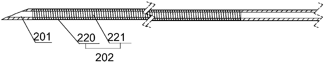
[0056] Such as Figure 1-2 ,and Figure 6 As shown, an in-situ fenestration instrument includes a puncture device 200, an adjustable bend catheter 100 and an anchor catheter 300, and the three are coaxially set in sequence; the adjustable bend catheter 100 is set outside the puncture device 200, and the anchor The fixed catheter 300 is sleeved on the outside of the adjustable bend catheter 100 . The three can be assembled by the user before the operation, or they can only be set together at the factory but not fixedly connected to each other, or they can be fixed or detachably fixed at the factory. connect. The puncture device 200 includes a puncture push rod 202 , a puncture needle 201 disposed at a distal end of the puncture push rod 202 , and a puncture handle 205 disposed at a proximal end of the puncture push rod 202 . The adjustable bend catheter 100 includes a hollow bend-adjusting catheter body 110 , a traction assembly 120 disposed inside the bend-adjusting cathete...

Embodiment approach

[0089] Such as Figure 11 As shown, the first embodiment: the distal end of the anchor 320 is fixed at the distal nozzle of the anchoring catheter body 310, and a plurality of braided wire ends 321 surround the distal nozzle of the anchoring catheter body 310 The wall is arranged around a circle, so that the distal nozzle of the anchoring catheter body 310 can form a through hole 330, which is the puncture hole for the needle head of the puncture needle to pass through. Each braided wire starts from the end 321 fixed on the distal nozzle of the anchoring catheter body 310, first extends to the outer side of the distal end, and reverses after reaching the inner wall 900 of the blood vessel, so that the side wall 322 of the anchoring member 320 Support the inner wall 900 of the blood vessel to form a stable anchor and support. The proximal end of the anchor 320 can be set as a free end 323, that is, the proximal end of each braided wire does not have to be fixed on the anchorin...

Embodiment 2

[0102] The structure of the in-situ fenestration device in Embodiment 2 is basically the same as that in Embodiment 1. The difference is that in the in-situ fenestration device in Embodiment 2, the anchor 320 consists of an anchor The catheter body 310 is composed of a plurality of struts arranged at the distal end. details as follows:

[0103] Such as Figure 17-18 As shown, the anchor 320 is composed of a plurality of struts 301 arranged axially symmetrically at the distal end of the anchoring catheter body 310 , and each strut 301 extends from the distal end of the anchoring catheter body 310 to the surroundings. Each support rod 301 can be a straight rod, or have a certain curvature after heat-setting treatment. Each strut 301 extends from the distal end of the anchoring catheter body 310 to the surroundings, and is supported on the inner wall 900 of the blood vessel. The end of each strut 301 is fixed on the distal end of the anchoring catheter tube body 310, and can b...


PUM

PropertyMeasurementUnit
Lengthaaaaaaaaaa

Abstract

The invention discloses an in situ fenestration instrument. The instrument comprises a puncture device, a bending-adjustable catheter and an anchoring catheter which are coaxially sleeved in sequence;the puncture device comprises a puncture push rod, a puncture needle head and a puncture handle; the bending-adjustable catheter comprises an bending-adjustment catheter body, a traction assembly anda bending-adjustment mechanism, the far end of the traction assembly is connected to the far end of the bending-adjustment catheter body, and the near end of the traction assembly is connected to thebending-adjustment mechanism; the anchoring catheter comprises a hollow anchoring catheter body and an anchoring piece arranged at the far end of the anchoring catheter body; the anchoring piece is made of an elastic material and has a contracted state and an expanded state; and the anchoring piece is axially provided with a through hole corresponding to the far end of the anchoring catheter body, and the anchoring piece is provided with at least one aperture which axially passes through the anchoring piece. According to the invention, the bending-adjustable catheter and the anchoring catheter can perform accurate positioning, ensure the puncture accuracy, and be used for retrograde in situ fenestration and antegrade in situ fenestration without influencing blood supply during fenestration.

Description

technical field [0001] The invention belongs to the field of medical devices, and relates to an intracavity interventional device, in particular to an in-situ fenestration device. Background technique [0002] With the continuous development of endovascular reconstruction surgery, the application of covered stents is also increasing, but the use of covered stents in some special parts will affect the blood supply of arterial branch vessels, such as the aortic arch, celiac trunk, and bilateral renal arteries. and superior mesenteric artery. The application of covered stents in these parts is greatly limited, and can only be improved through surgical methods, such as hybrid surgery, or equipment improvements, such as modular stents, pre-fenestrated stents, branch stents, multi-layer bare stents and other technical solutions to accommodate individual patient differences. However, for the case of aortic arch lesion, due to the extremely complex anatomical structure of the aort...

Claims


Application Information

Patent Timeline
IPC IPC(8): A61F2/07
Inventor 李阳张庭超
Owner HANGZHOU WEIQIANG MEDICAL TECH CO LTD
Why Eureka
Try Eureka