Endovascular anchoring catheter
A catheter and anchoring technology, applied in the field of intraluminal anchoring catheters and intraluminal interventional devices, can solve the problems of not being able to ensure the central position of the opening of the puncture point, unable to find the puncture point retrogradely, and difficult to puncture the membrane, and achieve savings. Operation time, improve the accuracy of puncture, prevent the effect of retraction
- Summary
- Abstract
- Description
- Claims
- Application Information
AI Technical Summary
Problems solved by technology
Method used
Image
Examples
Embodiment 1
[0042] The intraluminal anchoring catheter provided in Embodiment 1 of the present invention is used to assist puncture to puncture the membrane of a stent-graft. The puncture needle can be movably set in the intraluminal anchoring catheter to realize the delivery, guidance and positioning of the puncture needle.
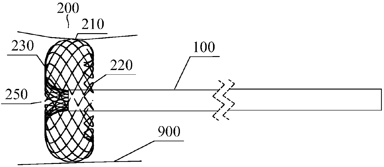
[0043] See figure 1 , the intraluminal anchoring catheter includes a hollow catheter tube body 100 and an anchor member 200 disposed at the distal end of the catheter tube body 100 . A puncture needle (not shown) is movably inserted in the catheter tube 100 . The anchor 200 expands radially outward from the catheter tube 100 in a natural state. After being expanded, the anchor 200 can be supported on the inner wall of the blood vessel to limit the radial movement of the catheter tube body 100 and the puncture needle passing through the catheter tube body 100 . Therefore, after the puncture needle passes through the distal opening of the catheter tube body 100, th...
Embodiment approach
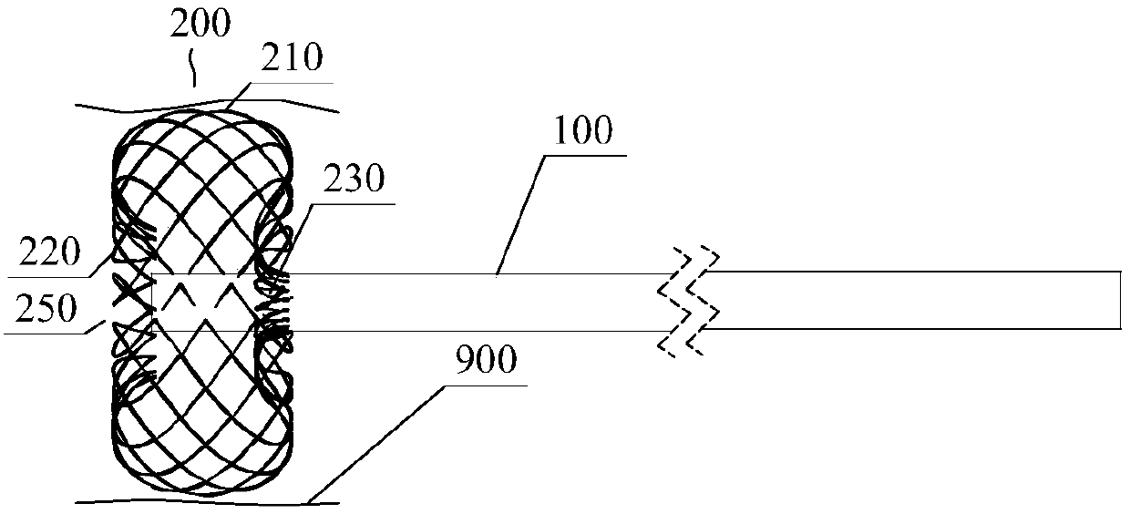
[0051] Such as figure 1 As shown, the first embodiment: the distal end of the anchor 200 is fixed at the distal nozzle of the catheter tube body 100, and a plurality of braided wire ends 230 are arranged around the tube wall of the catheter tube body 100 distal nozzle, Thus, the distal nozzle of the catheter tube body 100 can form a through hole 250, which is a puncture hole through which the needle of the puncture needle passes. Each braided wire starts from the end 230 fixed on the distal nozzle of the catheter tube body 100, first extends to the outer side of the distal end, and reverses after reaching the inner wall 900 of the blood vessel, so that the side wall 210 of the anchor 200 supports the blood vessel On the inner wall 900, a stable anchor and support is formed. The proximal end of the anchor 200 can be set as a free end 220, that is, the proximal end of each braided wire does not have to be fixed on the catheter tube body 100, so as to form a columnar or disc-sha...
Embodiment 2
[0056] The structure of the intraluminal anchoring catheter in the second embodiment is basically the same as the structure of the intraluminal anchoring catheter in the first embodiment, the difference is that the anchor 300 in the second embodiment consists of a Consists of multiple rods. Specifically, the structure of the anchor 300 has multiple implementations, as follows:
[0057] Such as Figure 6-9 As shown, the first embodiment is: the anchor 300 is composed of a plurality of struts 301 arranged axially symmetrically at the distal end of the catheter tube body 100 , and each strut 301 extends from the distal end of the catheter tube body 100 to the surroundings. Each support rod 301 can be a straight rod, or have a certain curvature after heat-setting treatment. Each strut 301 extends around from the distal end of the catheter tube body 100 and is supported on the inner wall 900 of the blood vessel. The end of each strut 301 is fixed on the distal end of the cathete...
PUM
 Abstract
Description
Claims
Application Information
 - R&D
- Intellectual Property
- Life Sciences
- Materials
- Tech Scout
- Unparalleled Data Quality
- Higher Quality Content
- 60% Fewer Hallucinations
Browse by: Latest US Patents, China's latest patents, Technical Efficacy Thesaurus, Application Domain, Technology Topic, Popular Technical Reports.
© 2025 PatSnap. All rights reserved.Legal|Privacy policy|Modern Slavery Act Transparency Statement|Sitemap|About US| Contact US: help@patsnap.com


