Current control circuit and control method thereof

A technology of current control circuit and voltage regulation circuit, applied in the field of electronics, can solve problems such as difficulty, limited application range, and difficulty in meeting the needs of constant current control of bidirectional converters, and achieves a smooth current change without current spikes and oscillations. Effect

Active Publication Date: 2019-06-04
MORNSUN GUANGZHOU SCI & TECH
View PDF5 Cites 3 Cited by
  • Summary
  • Abstract
  • Description
  • Claims
  • Application Information

AI Technical Summary

Problems solved by technology

However, when this kind of control circuit is applied to a bidirectional converter, there are the following problems: 1. When the converter works in forward and reverse directions, the current direction on the current sampling resistor is opposite: when the converter works in reverse, the voltage obtained by the current sampling resistor When the converter is working in the forward direction, the voltage obtained by the current sampling resistor is negative, which requires a positive and a negative bandgap voltage reference source to make the control circuit of the converter work in the forward or reverse direction. Works well, but it is difficult to implement a negative bandgap voltage reference when the external power supply only has a positive voltage
2. When the converter is switching the working direction, it is necessary to switch the working direction of the bandgap voltage reference source, which will change the control circuit, and the electrical signal oscillation or electrical signal spike generated when the control circuit is changed will affect the error in the converter amplifier input, causing jitter or spikes in the current on the output side of the converter
[0005] In summary, the existing methods are difficult to meet the requirements of bidirectional converter constant current control, which limits its application range

Method used


Image

  • Current control circuit and control method thereof
  • Current control circuit and control method thereof
  • Current control circuit and control method thereof

Examples


no. 1 example

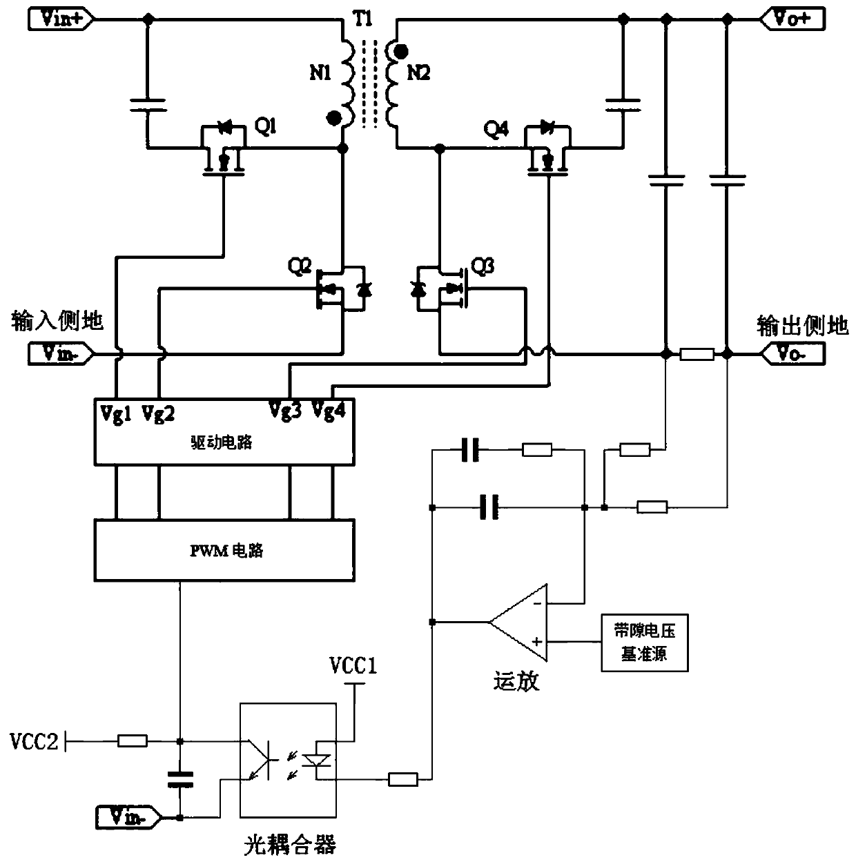
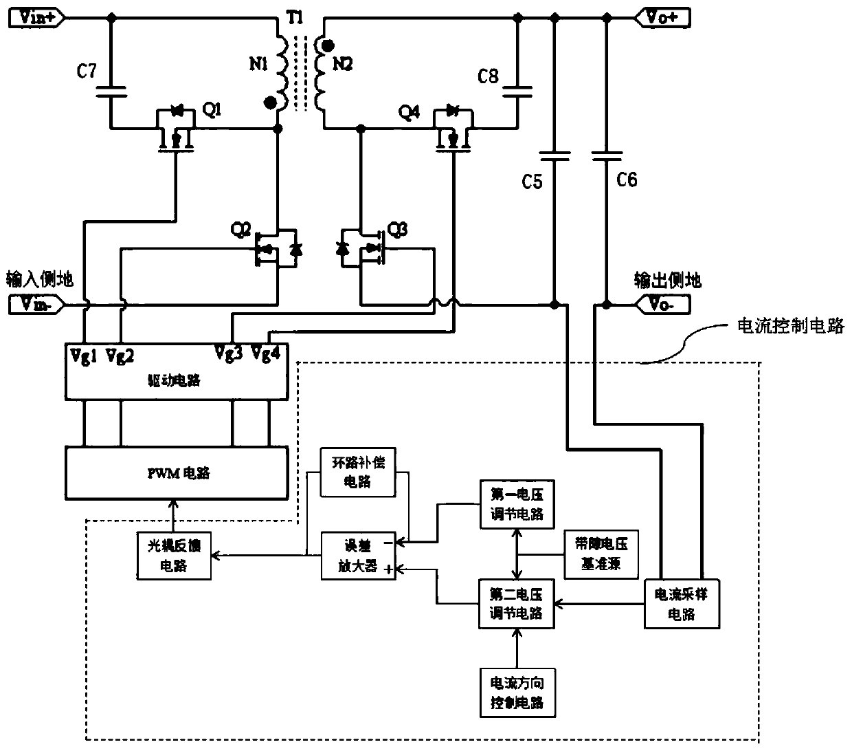
[0045] figure 2 It is a structural block diagram of the application of the circuit of the first embodiment of the current control circuit of the present invention to a bidirectional converter, image 3 It is a circuit schematic diagram of the application of the circuit of this embodiment to a bidirectional converter. As shown in the figure, the bidirectional converter includes a main power circuit, a drive circuit and a PWM circuit, and a current control circuit, including a current sampling circuit, which is used to sample the output side current and output to the second voltage regulation circuit; the first voltage regulation circuit is used to adjust the static operating point of the current control circuit; the second voltage regulation circuit is used to receive and process the voltage signal output by the current sampling circuit; the current direction control circuit is used to Adjusting the voltage bias generated by the second voltage regulation circuit for sampling t...

no. 2 example

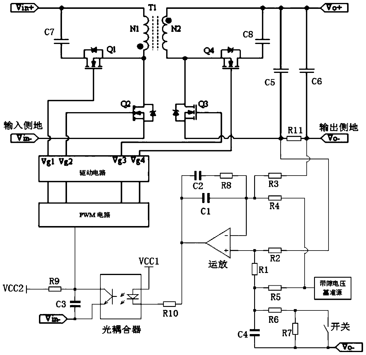
[0061] Figure 7 It is a structural block diagram of the second embodiment of the current control circuit of the present invention applied to a bidirectional converter, Figure 8 It is the schematic diagram of the circuit applied to the bidirectional converter in this embodiment. Compared with the first embodiment, the connection points of resistor R3 and resistor R4 are modified to be connected to the same-phase input terminal of the operational amplifier, and the connection points of resistor R1 and resistor R2 are modified. In order to connect with the inverting input terminal of the op amp, such modification makes the output of the second voltage regulating circuit and the output of the error amplifier invert; One end of C3 is connected to the PWM circuit as the output of the optocoupler feedback circuit, the other end of the capacitor C3 is connected to the ground on the input side, the resistor R9 is connected in parallel with the capacitor C3, and the collector of the o...


PUM


Abstract

The invention discloses a current control circuit, which acquires current information on the output side of a bidirectional converter by means of a current sampling circuit, uses the outputs of a first voltage regulating circuit and a second voltage regulating circuit as the input of an error amplifier, regards the output of the error amplifier as the input of an optocoupler feedback circuit, feeds back a current signal on the output side into a PWM circuit through conversion processing by means of various levels of circuits, controls a duty ratio of a switching tube on the input side of a main power circuit by means of a control circuit, and realizes constant current of on the output side. The current control circuit can ensure that the bidirectional converter has no current oscillation and current spike when the bidirectional converter switches an operating direction, can realize the constant current on the output side of the bidirectional converter when only using one forward bandgap voltage reference source, and is simple in circuit.

Description

technical field [0001] The invention belongs to the field of electronic technology and relates to a current control circuit for a bidirectional DC-DC converter. Background technique [0002] Because the bidirectional DC-DC converter can work forward or reverse, it can realize the bidirectional transmission of energy, that is, it allows the electric energy to be transferred from the defined input side to the output side, and also allows the electric energy to be transferred from the defined output side to the input side. Functionally equivalent to two unidirectional DC converters, it has a very wide range of applications in uninterruptible power supplies, battery charging and discharging, electric vehicles, energy recovery systems for high-power equipment, and backup power for high-power equipment. [0003] The bidirectional converter can define two working directions. When working in the forward direction, the energy is transferred from the input side to the output side; whe...

Claims


Application Information

Patent Timeline
Patent Type & Authority Applications(China)
IPC IPC(8): H02M3/335
CPCH02M3/335
Inventor 李斌华李永昌
Owner MORNSUN GUANGZHOU SCI & TECH
Why Eureka
Try Eureka