Method for detecting load current

A load current and voltage technology, applied in the direction of measuring current/voltage, measuring electrical variables, measuring devices, etc., can solve the problem of large load current detection error

Active Publication Date: 2019-06-04
SOUTHCHIP SEMICON TECH SHANGHAI CO LTD
View PDF5 Cites 0 Cited by
  • Summary
  • Abstract
  • Description
  • Claims
  • Application Information

AI Technical Summary

Problems solved by technology

[0003] The purpose of the present invention is to provide a method for detecting load current, which mainly solves the problem of large detection error of existing load current existing in the prior art

Method used


Image

  • Method for detecting load current
  • Method for detecting load current
  • Method for detecting load current

Examples


Embodiment

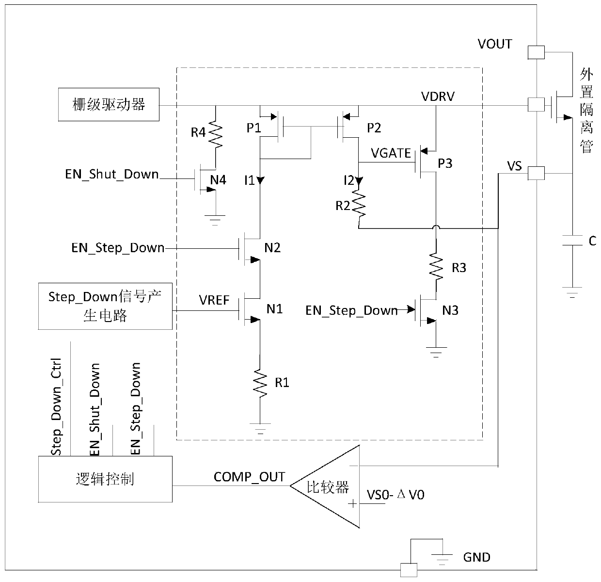
[0023] Such as Figure 1 to Figure 7 As shown, a method for detecting load current includes a control circuit for detecting load current, the control circuit includes a comparator, a logic control circuit connected to the COMP_OUT terminal of the comparator, and a signal generation circuit connected to the Step_Down_Ctrl pin of the logic control circuit , a signal generation circuit connected to the logic control circuits EN_Shut_Down and EN_Step_Down and an isolation tube grid control circuit, a gate driver connected to the isolation tube grid control circuit, an external isolation tube connected to the grid and the isolation tube grid control circuit, One end is connected to the drain of the external isolation tube, the other end is grounded and the capacitor C is connected to the external load, connected to the positive input of the comparator and passed the threshold voltage VS0-ΔV0 of the set voltage threshold, and connected to the comparator at the same time through the s...


PUM


Abstract

The invention discloses a method for detecting a load current. In the prior art, an existing load current detection error is large. In the invention, the above problem is mainly solved. The method comprises the following steps of (S1) accessing a threshold voltage VS0-deltaV0 provided with a voltage threshold to a positive input end of a comparator, and accessing a VS voltage of a voltage on a detecting capacitor C to a negative input end of the comparator; (S2) comparing the threshold voltage VS0-deltaV0 with the VS voltage in a fixed time interval through the comparator; and (S3) when the VSvoltage is less than the threshold voltage VS0-deltaV0, outputting a high level by the comparator, wherein at this time, the voltage of the capacitor C drops significantly, which indicates that the load current of a load connected to the capacitor C is large, otherwise, the load current of the load connected to the capacitor C is small. In the above scheme, the load current in a circuit can be accurately determined and a high practical value and a high popularization value are achieved.

Description

technical field [0001] The invention belongs to the technical field of integrated circuits, and in particular relates to a method for detecting load current. Background technique [0002] In the charging system, it is generally judged by detecting the magnitude of the load current whether the load terminal is fully charged or whether it has been unplugged. The existing technology basically judges the load size by directly sampling the current on the charging path. There are two general methods: the first is to connect a sense resistor in series on the charging path, and the circuit will measure the voltage across the sense resistor. The second is to directly sample the voltage difference between the two ends of the isolation tube. The first way (such as figure 1 As shown), the charging device controls the entire charging process by controlling the gate VDRV voltage of the isolation tube. In order to stabilize the input voltage of the charging load, a load capacitor of seve...

Claims


Application Information

Patent Timeline
IPC IPC(8): G01R19/00
Inventor 肖哲飞
Owner SOUTHCHIP SEMICON TECH SHANGHAI CO LTD
Why Eureka
Try Eureka