
Lateral jetting device

A transmission device and locking device technology, applied in printing, typewriters, etc., can solve problems such as inkjet head damage, achieve cost reduction, prevent detachment from guide rails, and maintain a constant distance

Pending Publication Date: 2019-06-04
CHANGZHOU SINAJET SCI & TECH
View PDF0 Cites 0 Cited by
  • Summary
  • Abstract
  • Description
  • Claims
  • Application Information

AI Technical Summary

Problems solved by technology

[0003] In order to solve the problem in the prior art that printing marks from the bottom is easy to cause damage to the inkjet head, the present invention provides a side spray device that can print the reverse side and protect the nozzle assembly

Method used

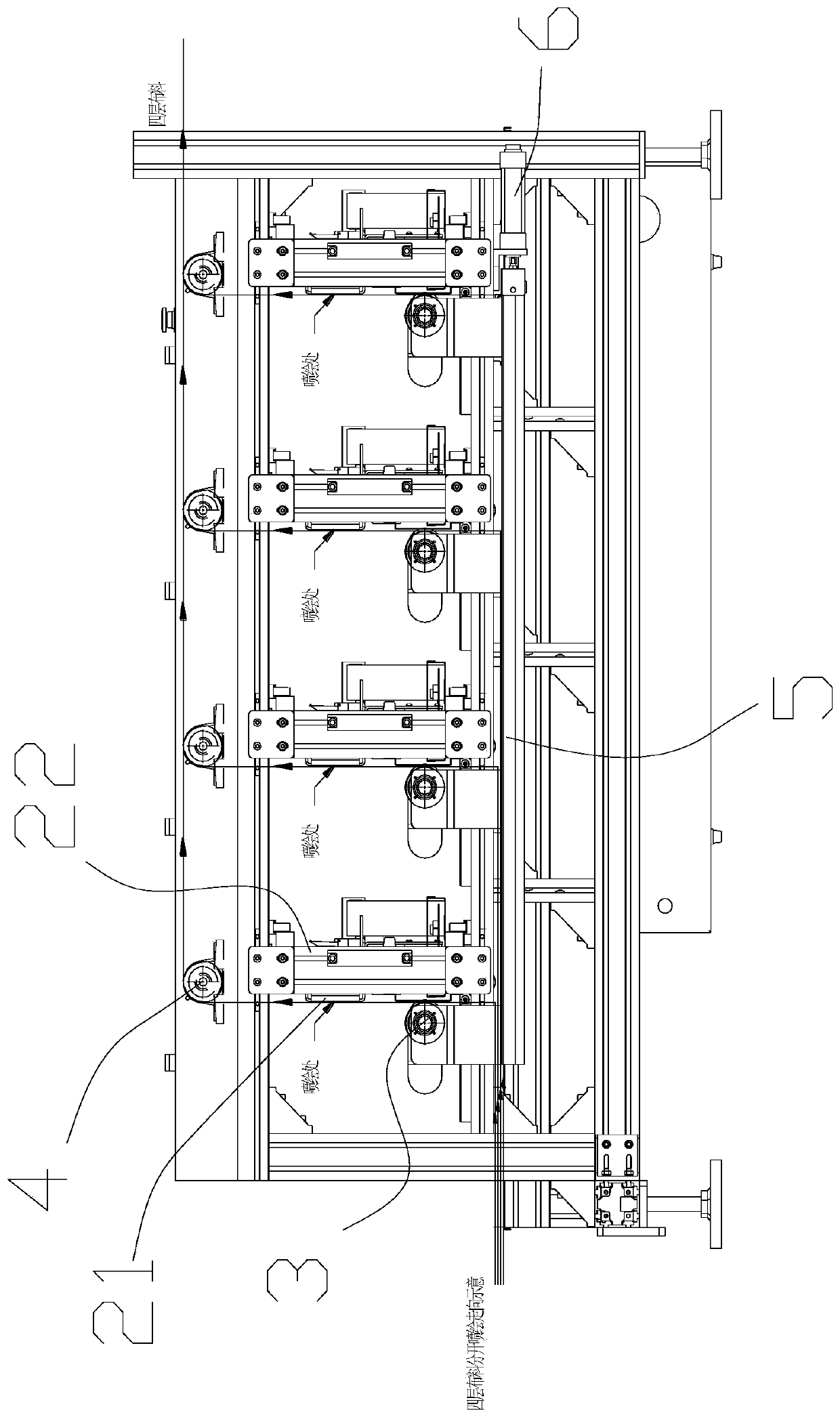
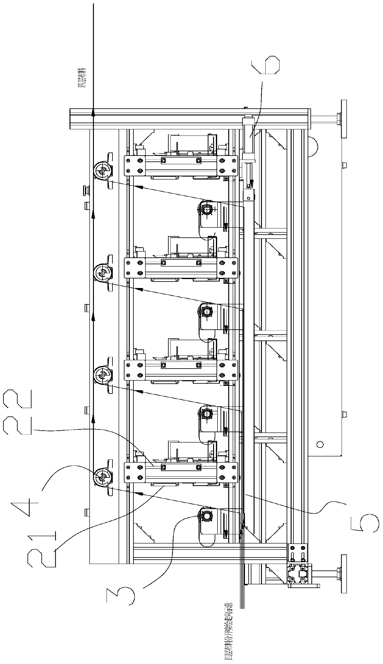

Image

  • Lateral jetting device
  • Lateral jetting device
  • Lateral jetting device

Examples


Embodiment Construction

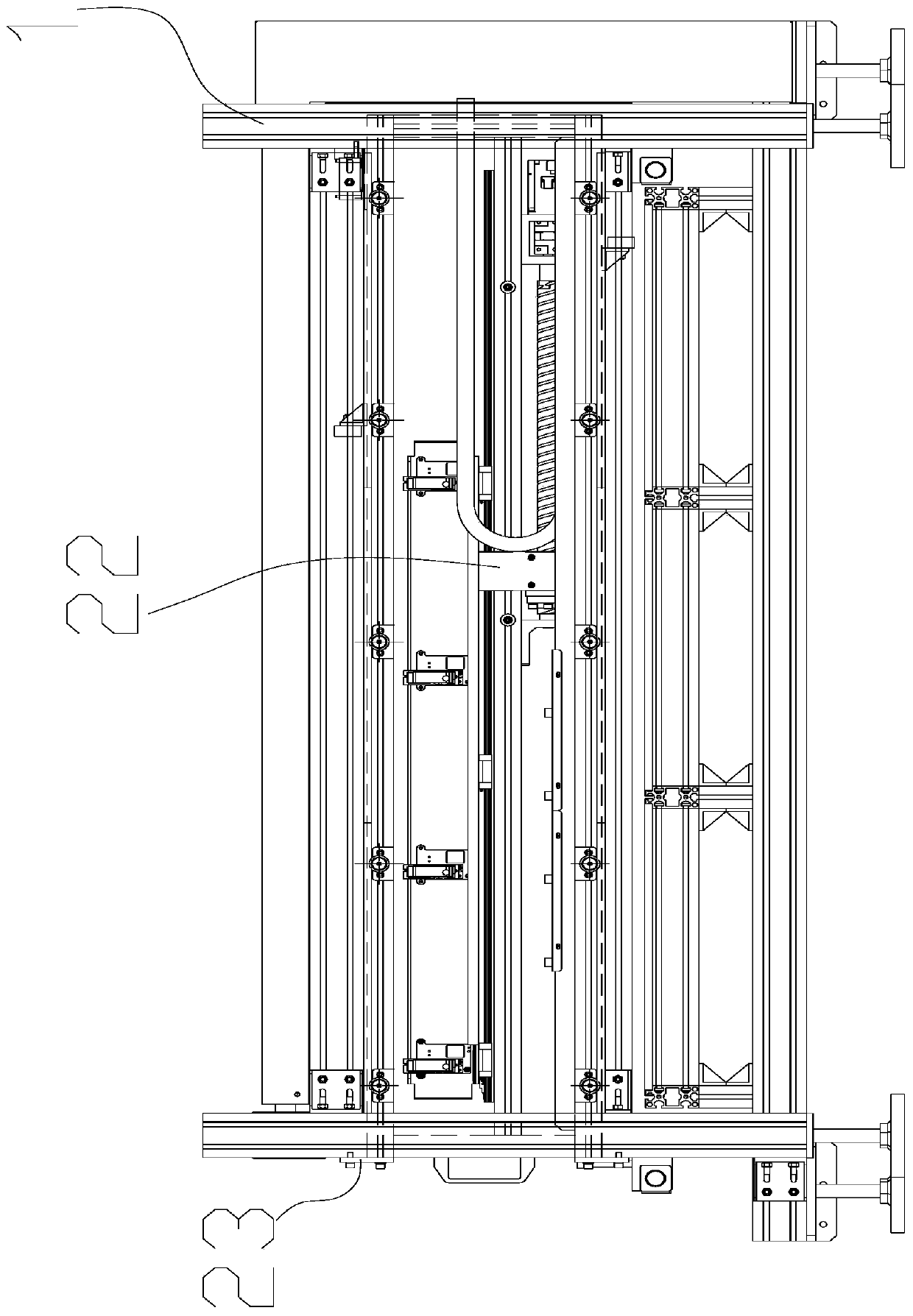
[0033] Such as Figure 1-7 , a kind of side spraying device, comprises frame 1, is provided with several side spraying units 2 on the frame 1, and the number of side spraying units 2 can be set according to actual production demand, and side spraying unit 2 includes along several nozzle assemblies 21 , the spraying direction of the spray head assembly 21 is set along the horizontal direction, and the transmission device for conveying the sheet material is also provided on the frame 1. The transmission device includes a movable roller 3 arranged on one side of the side spray unit 2 correspondingly, and the movable roller 3 It is arranged on the side of the inkjet head close to the nozzle assembly 21, and the sheet material is transported to the vicinity of the inkjet head through the movable roller 3, and the sheet material in the ejected state is arranged in the vertical direction. Lead-in or lead-out power roller 4.

[0034] The side spray unit 2 includes a sliding table 22 ...


PUM


Abstract

The invention relates to the technical field of printing equipment, in particular to a lateral jetting device. The lateral jetting device comprises a rack, a plurality of lateral jetting units are arranged on the rack, the lateral jetting units comprise a plurality of nozzle assemblies, the jetting directions of the nozzle assemblies are arranged in the horizontal direction, the rack is further provided with a transporting device used for transporting slice-shaped materials, the transporting device comprises movable rollers arranged on one sides of the lateral units in a one-to-one corresponding mode, the movable rollers are arranged on the side, close to the nozzle assemblies, of ink jetting heads, the slice-shaped materials are transported to close to the ink jetting heads passing through the movable rollers, the slice-shaped materials in a jetting state are arranged on the vertical direction, and the rack is further provided with power rollers used for introducing or eliciting the materials. According to the lateral jetting device, a lateral jetting mode is adopted to jetting, jetting is conducted on the back surface of the slice-shaped materials, and meanwhile the problem of nozzles are prone to being burned out is solved.

Description

technical field [0001] The invention relates to the technical field of printing equipment, in particular to a side spray device. Background technique [0002] In some special applications, such as the wind power industry, since there are four layers of materials that need to be printed and marked on the reverse side of each layer, and the material is facing up when discharging, it is impossible to print the mark on the reverse side of each layer of material , so it is not feasible to print the mark on the front; if the mark is printed on the bottom, the inkjet head is easy to be burned and damaged, which is difficult to achieve. Contents of the invention [0003] In order to solve the problem in the prior art that printing marks from the bottom easily causes damage to the inkjet head, the present invention provides a side spraying device capable of printing on the reverse side and protecting the nozzle assembly. [0004] The technical solution adopted by the present inven...

Claims


Application Information

Patent Timeline
Patent Type & Authority Applications(China)
IPC IPC(8): B41J2/01B41J3/407
Inventor 王福康徐芬
Owner CHANGZHOU SINAJET SCI & TECH
Learn More