
Calibration device and method for laser displacement measurement system

A measurement system and laser displacement technology, applied in the direction of measuring devices, optical devices, instruments, etc., can solve the problems of increased calibration time, failure to reflect the real status of the stiffness measuring instrument, equipment damage, etc., and achieve the effect of ensuring product quality

Active Publication Date: 2019-05-31
JINCHENG NANJING ELECTROMECHANICAL HYDRAULIC PRESSURE ENG RES CENT AVIATION IND OF CHINA
View PDF6 Cites 0 Cited by
  • Summary
  • Abstract
  • Description
  • Claims
  • Application Information

AI Technical Summary

Problems solved by technology

[0004] The purpose of the present invention: to provide a laser displacement measurement system calibration device and calibration method, which is used to calibrate the laser displacement measurement system on the high-precision stiffness measuring instrument, and solve the problem that the calibration results of the above-mentioned traditional sensors cannot reflect the real situation of the stiffness measuring instrument problems, and avoid the occurrence of various problems such as equipment damage, calibration time increase, and cost doubling due to the difficulty of disassembly technology

Method used


Image

  • Calibration device and method for laser displacement measurement system
  • Calibration device and method for laser displacement measurement system
  • Calibration device and method for laser displacement measurement system

Examples


Embodiment Construction

[0023] The present invention will be further described in detail through specific embodiments below.

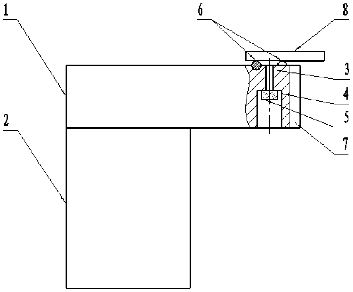
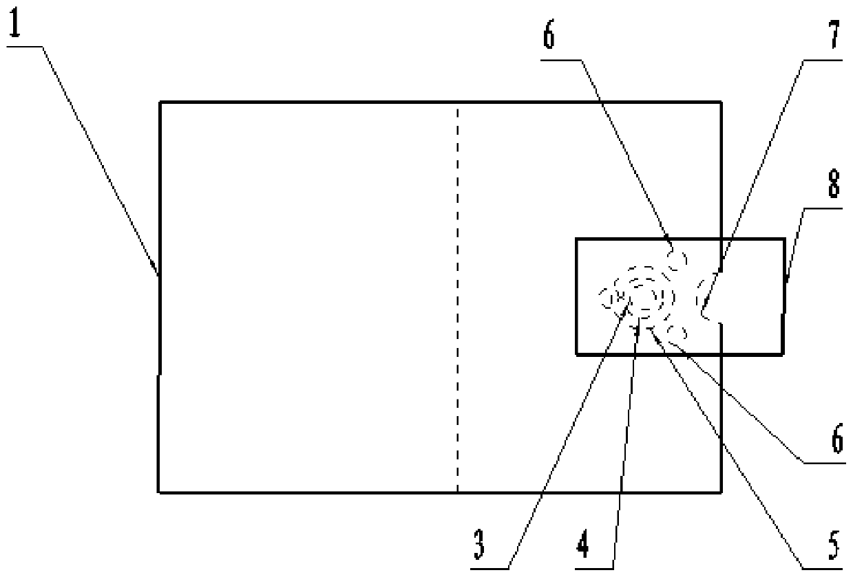
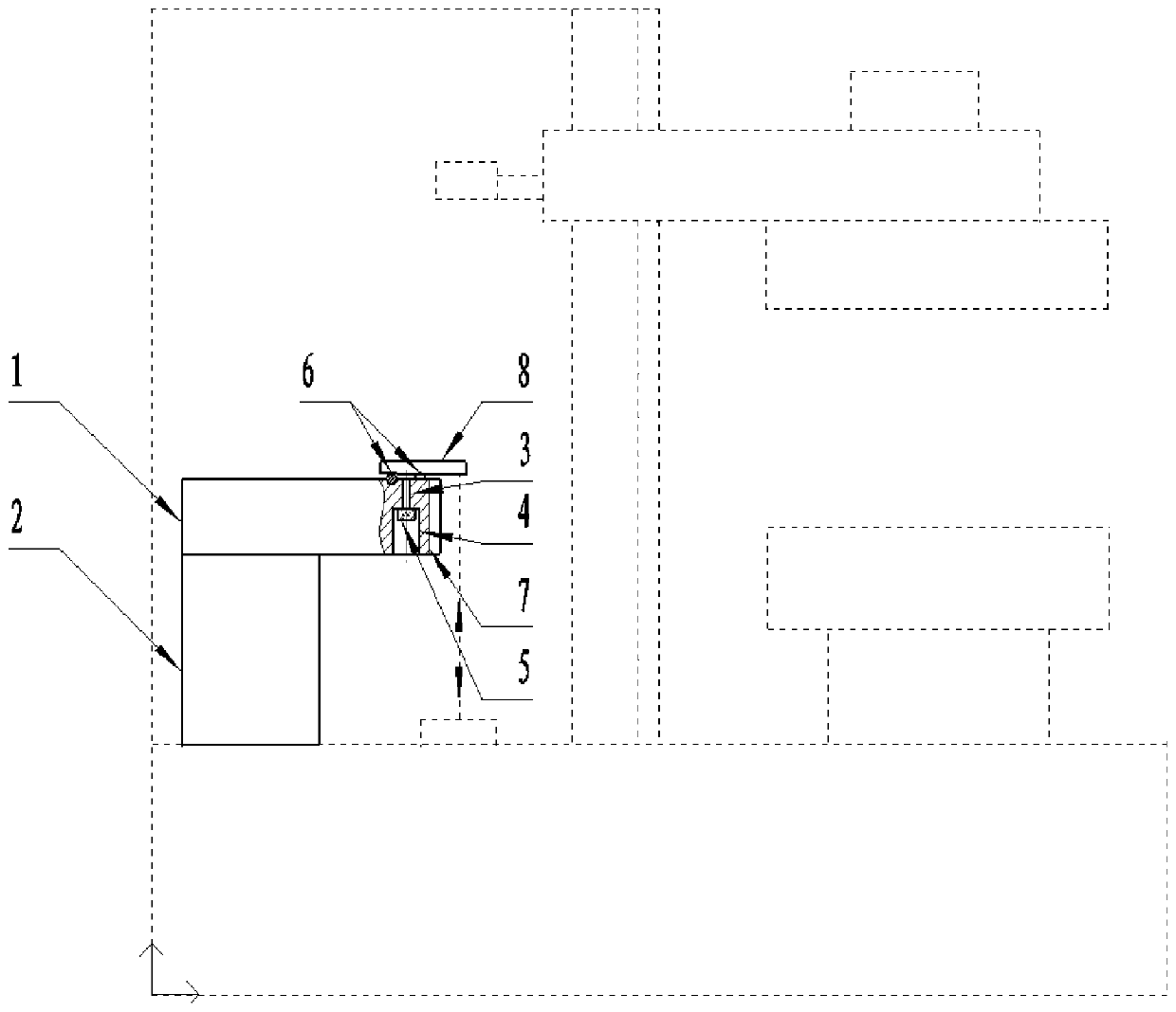
[0024] A laser displacement measurement system calibration device, used to calibrate the laser displacement measurement system on a high-precision stiffness measuring instrument, it includes a workbench, and the workbench includes cuboid one (1), cuboid two (2), cuboid one The length of (1) is greater than the length of cuboid two (2), and the lower surface of cuboid one (1) fits with the upper surface of cuboid two (2); The left side of cuboid two (2) and cuboid one (1) The left sides are flush, and cuboid one (1) and cuboid two (2) form an inverted L-shaped structure as a whole; the gauge block group includes five gauge blocks (8) with different thicknesses, and the thickness of the gauge blocks (8) ranges from small to In large increments, the size difference between the thinnest and thickest gauge blocks (8) just covers the working range of the laser displacement measurem...


PUM


Abstract

The invention discloses a calibration device and method for a laser displacement measurement system, and the device and method are used for carrying out on-site calibration on the laser displacement measurement system on a high-precision rigidity measurement instrument, and belong to the field of measurement and test standards. According to the invention, a gauge block is reliably positioned and conveniently placed on the three beads through a workbench tool and a three-bead measuring mechanism with magnetism, so that the problem that the measurement precision is influenced by the gas film generated between the gauge block and the three-bead measuring mechanism due to installation, repeated positioning of the gauge block and the like is solved, and the field calibration of the laser displacement measurement system is realized.

Description

technical field [0001] The invention relates to a calibration device and a calibration method for a laser displacement measurement system, which are used for calibrating a laser displacement measurement system on a high-precision stiffness measuring instrument, and belong to the field of measurement and testing standards. Background technique [0002] The electromechanical system has a large number of high-precision (force value indication error ±0.5%, displacement indication error ±1μm), small displacement (range 0-2mm) static load stiffness measuring instruments (hereinafter referred to as stiffness measuring instruments), these stiffness measuring instruments It is mainly used for the static stiffness measurement of elastic elements, and the measurement of force and micro-deformation is realized through the force value measurement system and the laser displacement measurement system. At present, there is no unified calibration specification and method for this type of equ...

Claims


Application Information

Patent Timeline
Patent Type & Authority Applications(China)
IPC IPC(8): G01B11/02
Inventor 项勇郝定武郭萃堃
Owner JINCHENG NANJING ELECTROMECHANICAL HYDRAULIC PRESSURE ENG RES CENT AVIATION IND OF CHINA
Learn More