
Cavity filter device and cavity cover plate assembly thereof

A cavity filter and cover plate technology, which is applied to waveguide devices, electrical components, circuits, etc., to achieve the effects of miniaturization, lower resonance frequency, and low cost

Pending Publication Date: 2019-05-28
COMBA TELECOM TECH (GUANGZHOU) CO LTD +1
View PDF4 Cites 3 Cited by
  • Summary
  • Abstract
  • Description
  • Claims
  • Application Information

AI Technical Summary

Problems solved by technology

[0004] Based on this, it is necessary to address the defects of existing metal cavity filters and provide a cavity filter device and cavity cover assembly that can achieve miniaturization, light weight, and low cost while ensuring excellent electrical indicators

Method used


Image

  • Cavity filter device and cavity cover plate assembly thereof
  • Cavity filter device and cavity cover plate assembly thereof
  • Cavity filter device and cavity cover plate assembly thereof

Examples


Embodiment Construction

[0026] In order to facilitate the understanding of the present invention, the present invention will be described more fully below with reference to the associated drawings. Preferred embodiments of the invention are shown in the accompanying drawings. However, the present invention can be embodied in many different forms and is not limited to the embodiments described herein. On the contrary, these embodiments are provided to make the understanding of the disclosure of the present invention more thorough and comprehensive.

[0027] It should be noted that when an element is referred to as being “fixed” to another element, it can be directly on the other element or there can also be an intervening element. When an element is referred to as being "connected to" another element, it can be directly connected to the other element or intervening elements may also be present. The terms "vertical," "horizontal," "left," "right," and similar expressions are used herein for purposes ...


PUM


Abstract

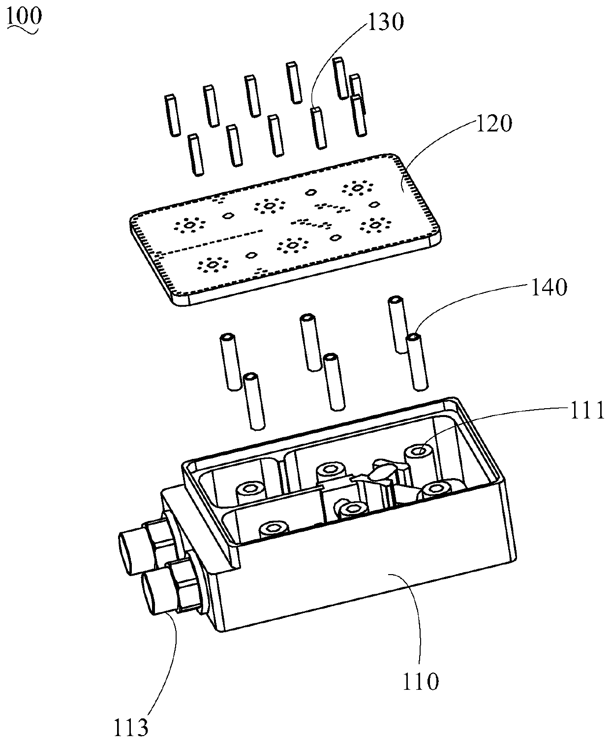
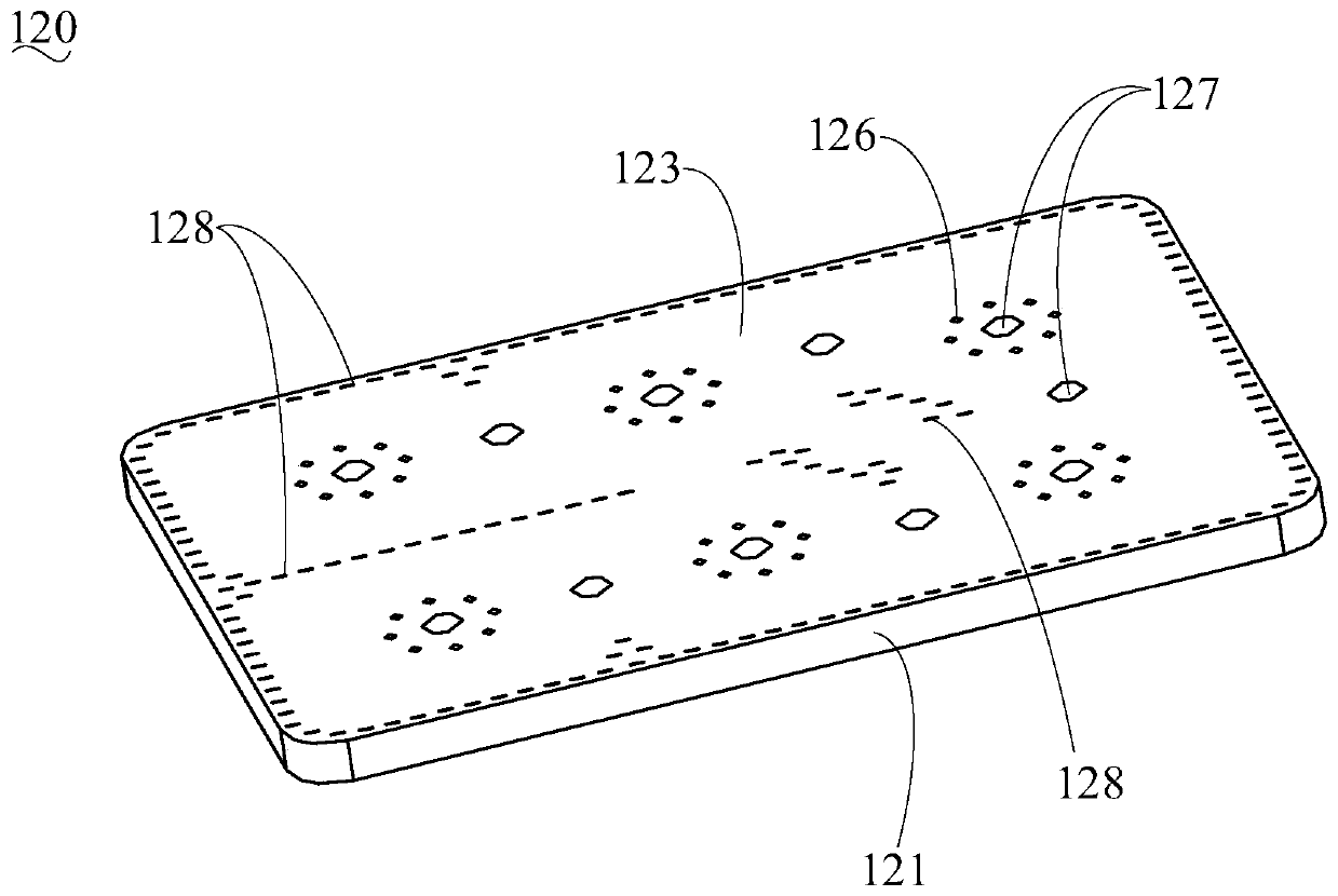
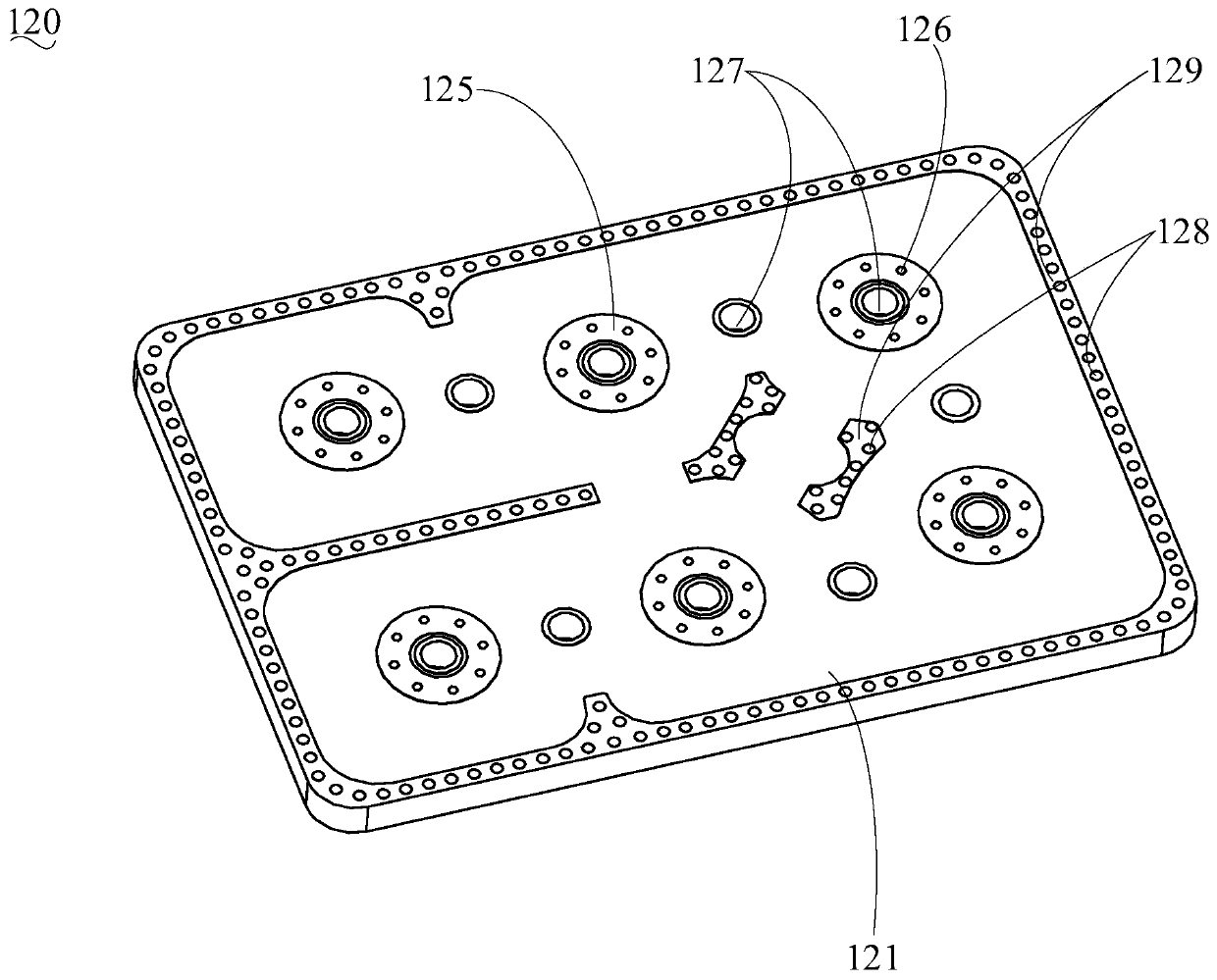
The invention relates to a cavity filter device and a cavity cover plate assembly thereof. A cover plate comprises a substrate, a metal layer covering the outer surface of the substrate and metal sheets formed on the inner surface of the substrate. Debugging via holes are formed in the positions, corresponding to resonant cavities and a coupling channel, of the cover plate. The cover plate of a printed board structure is adopted to replace a traditional metal cover plate, the metal layer is matched with the metal cavity to form a closed shielding space, and the metal sheets are coupled or electrically connected with the corresponding resonant columns, so that the resonant frequency is effectively reduced. Therefore, under the condition that the movable resonant column with the disc is notused, the corresponding index requirement can be met, and therefore only the metal cavity with small height is needed. By controlling the depth of a tuning rod inserted into the metal cavity, the adjustable resonant frequency and coupling amount can be realized. Moreover, the surplus part of the tuning rod is sheared, and the tail end of the tuning rod is flush with the outer surface of the coverplate. Therefore, the cavity filter device can realize miniaturization, light weight and low cost while ensuring excellent electrical indexes.

Description

technical field [0001] The invention relates to the technical field of mobile communication, in particular to a cavity filter device and a cavity cover assembly thereof. Background technique [0002] The introduction of 5G Missive MIMO technology has greatly increased the number of filters integrated with antennas, and put forward higher requirements for the weight, volume, and cost of filters. At present, common types of base station filters include metal cavity filters and ceramic dielectric filters. Although ceramic dielectric filters have the advantages of light weight and small size, the current process development is not mature enough, and the consistency and cost of mass production are relatively high. big challenge. At present, in order to promote the construction of 5G faster, miniaturized metal cavity filters have become the preferred transition solution. [0003] However, due to the requirements for small size, light weight and low cost of 5G filters, the miniat...

Claims


Application Information

Patent Timeline
Patent Type & Authority Applications(China)
IPC IPC(8): H01P1/208
Inventor 郭春波党志南金志刚龚见国
Owner COMBA TELECOM TECH (GUANGZHOU) CO LTD
Learn More