
Non-maximum suppression, dynamic threshold calculation and image edge detection method

A non-maximum value suppression and image edge technology, applied in the field of image processing, can solve the problem of inability to effectively distinguish star contour edge points from star surface texture edge points, the high computational complexity of the Canny edge detection algorithm, and the difficulty of increasing the center of mass of star objects. Complexity and other issues, to achieve the effect of easy hardware circuit implementation, simplified calculation complexity, and reduced complexity

Active Publication Date: 2019-05-28
HEFEI UNIV OF TECH
View PDF3 Cites 15 Cited by
  • Summary
  • Abstract
  • Description
  • Claims
  • Application Information

AI Technical Summary

Problems solved by technology

However, in the edge detection of deep space images, the algorithm cannot effectively distinguish the edge points of the star outline and the edge points of the star surface texture, which greatly increases the difficulty and complexity of the calculation of the center of mass of the star target.
In addition, the Canny algorithm uses dual thresholds to remove noise edge points, and it needs to calculate the high and low thresholds of the entire image, which makes the Canny edge detection algorithm computationally complex. In actual deep space detection, the image resolution is very high, and the entire The hardware resources required for the image are relatively large, which is not conducive to hardware implementation

Method used


Image

  • Non-maximum suppression, dynamic threshold calculation and image edge detection method
  • Non-maximum suppression, dynamic threshold calculation and image edge detection method
  • Non-maximum suppression, dynamic threshold calculation and image edge detection method

Examples


Embodiment 1

[0026] The image edge detection method of the present invention is especially suitable for occasions where it is necessary to effectively detect the edge points of the outline of the object in the image and to suppress the edge points of the surface texture of the object. In this embodiment, the method of the present invention is described in detail by taking the edge detection of a star against a deep space background as an example.

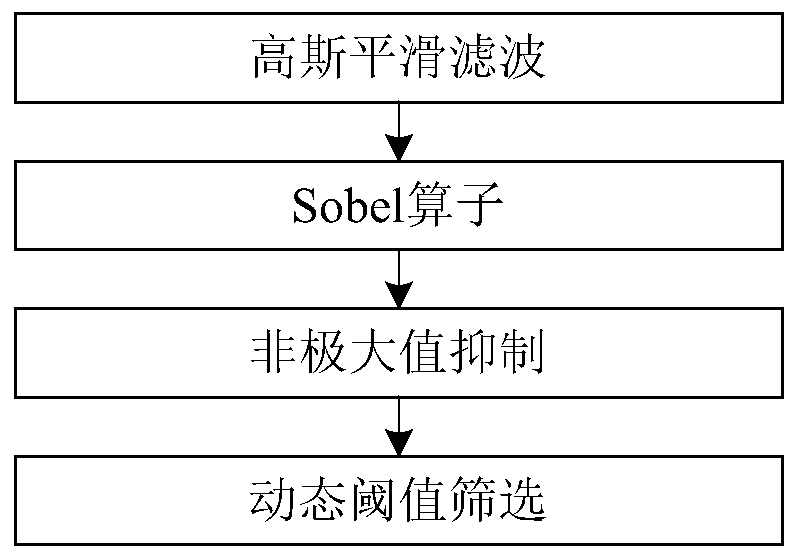
[0027] Such as figure 1 As shown, a star edge detection method for deep space background, including the following steps:

[0028] 1) Perform Gaussian smoothing filtering on each pixel in the original image, wherein the Gaussian smoothing filter uses a 3×3 convolution template, and performs Gaussian smoothing filtering through formula (1) to obtain a smooth image g(x, y);

[0029]

[0030] 2) Acquiring the gradient of each pixel in the Gaussian filtered image according to the Sobel operator to obtain the gradient image, wherein the Sobel oper...


PUM


Abstract

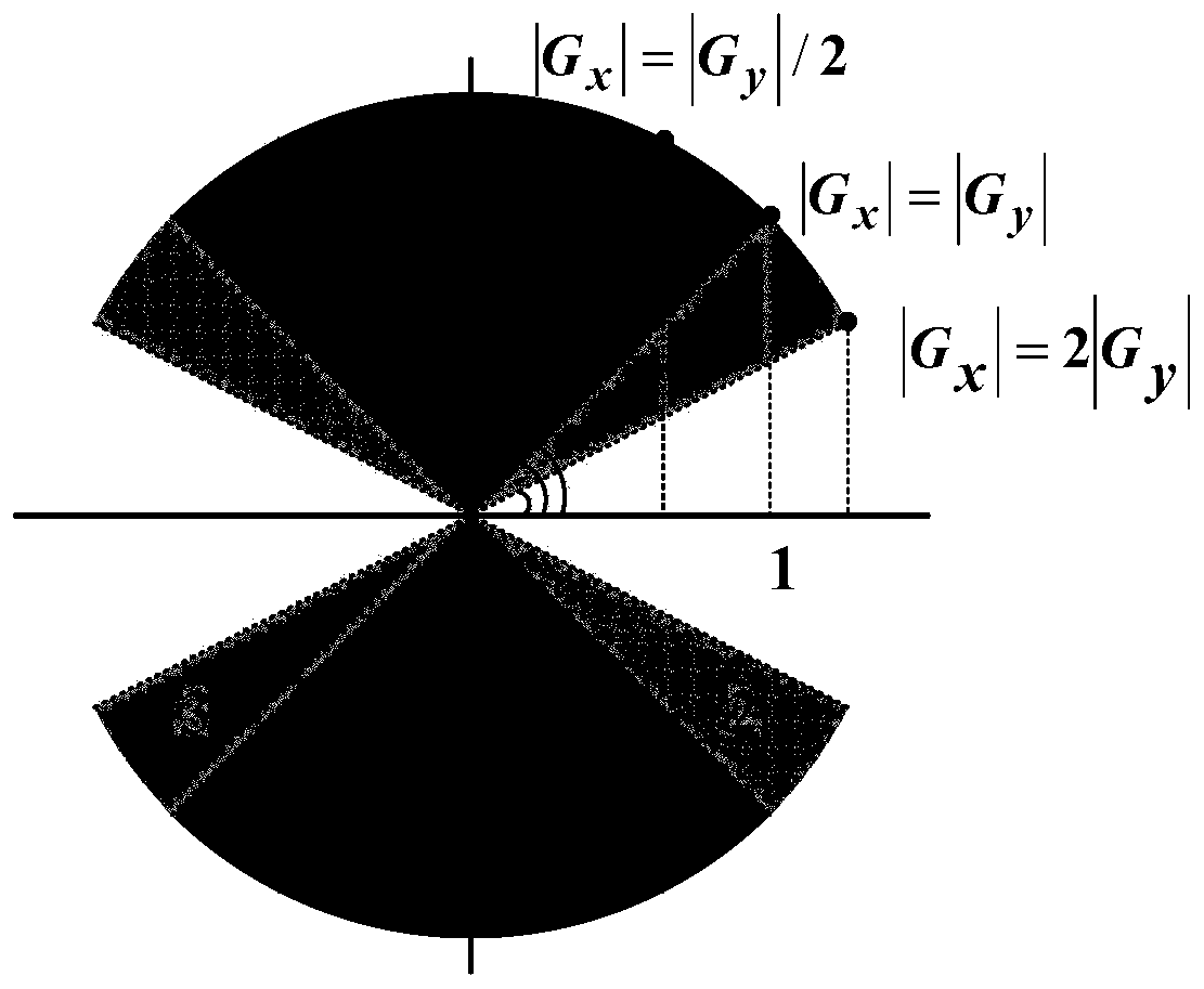
The invention discloses a non-maximum suppression, dynamic threshold calculation and image edge detection method. The detection method comprises the following steps: eliminating Gaussian noise in an original image by Gaussian filtering; obtaining the gradient of each pixel point of the image obtained after Gaussian filtering; carrying out non-maximum suppression processing by utilizing the gradient amplitude and the gradient direction of each pixel point to obtain a candidate edge image, marking pixel points serving as candidate edge points in the candidate edge image, calculating a dynamic threshold value of a target body contour edge point in the image, and screening the candidate edge points by using the dynamic threshold value to obtain an edge image. According to the invention, the gradient direction is determined by comparing the gradient amplitudes in the horizontal direction and the vertical direction; Therefore, the calculation of the gradient direction angle is avoided, the calculation complexity of edge detection is simplified, the dynamic threshold calculation method can effectively distinguish the pseudo edge and the contour edge of the target body caused by the surface texture of the target body in the image, and more accurate edge information is provided for target body identification.

Description

technical field [0001] The invention relates to the field of image processing, in particular to an image edge detection method. Background technique [0002] With the continuous development of aerospace technology, deep space exploration has become an important research direction. Optical autonomous navigation has become a key technology for deep space exploration because of its independence, low cost, high reliability, high accuracy and real-time performance. Optical autonomous navigation uses the optical sensor of the deep space probe to capture the image of the target star, and through the real-time image processing of the spaceborne equipment, extracts the edge point of the target star in the image, and uses the edge point information to calculate the barycenter position of the target star. for its orbital navigation controls. Therefore, edge detection of star objects in deep space images is one of the key technologies for optical autonomous navigation of deep space ex...

Claims


Application Information

Patent Timeline
Patent Type & Authority Applications(China)
IPC IPC(8): G06T7/13
Inventor 肖昊范彦铭史伟忠孔斯叶
Owner HEFEI UNIV OF TECH
Learn More