Electronic pen
An electronic pen and refill technology, applied in the direction of digital data processing, instruments, data processing input/output process, etc., can solve the problems of reducing the sensitivity of the electronic pen, large invalid travel, collapse, etc., to improve the writing experience, reduce the Collapsing feeling, the effect of eliminating invalid travel
- Summary
- Abstract
- Description
- Claims
- Application Information
AI Technical Summary
Problems solved by technology
Method used
Image
Examples
Embodiment 1
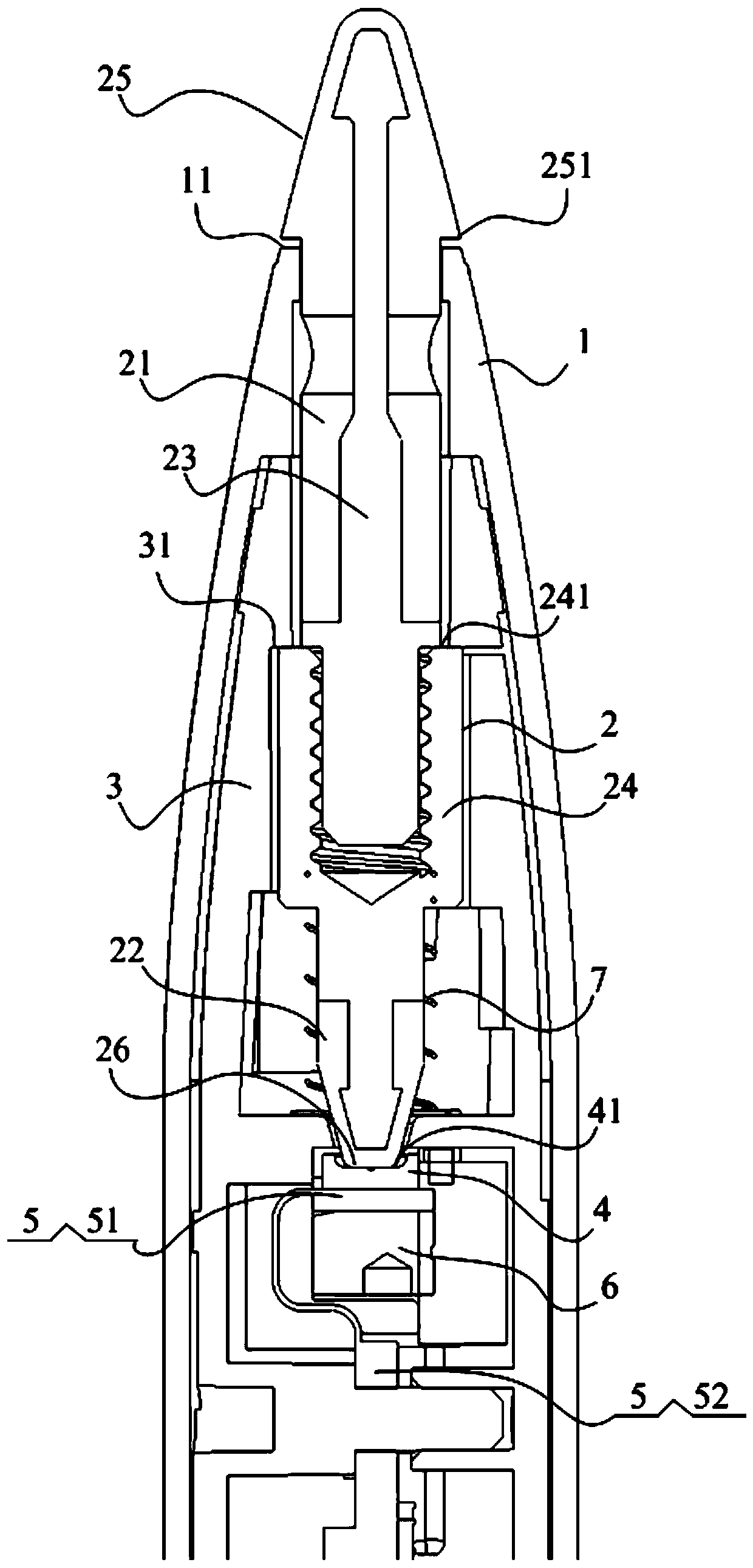
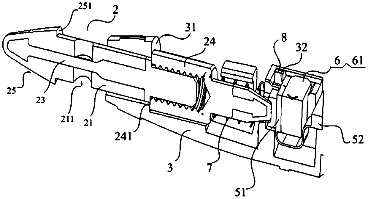
[0066] figure 1 and figure 2 The structural design of the electronic pen according to one embodiment of the present invention is shown.
[0067] In this embodiment, the electronic pen may include a main bracket 3, which is arranged in the pen tube 1 and used for installing various components of the electronic pen.
[0068] In this embodiment, the main bracket 3 can have a mounting groove 32, the pressure sensor 4 and the adjustment mechanism 6 are all installed in the mounting groove, and the pen core 2 is installed in the main bracket 3, wherein the pen tip 25 of the pen core 2 is located on the main bracket. The outside of the bracket 3, while the force application end 26 of the pen core 2 is located inside the main support 3, and the force application end 26 of the pen core 2 extends into the installation groove 32. This structure can position the pressure sensor 4 and the adjustment mechanism 6 in the pen tube 1 through the installation groove 32, which is conducive to ...
Embodiment 2
[0100] Figure 5 and Figure 6 The structural design of the electronic pen according to another embodiment of the present invention is shown.
[0101] The main difference between this embodiment and the first embodiment above is that the adjustment mechanism 6 is realized by a transmission pair 62 .
[0102] The transmission pair 62 can be a screw nut transmission pair, the transmission pair 62 can include an adjustment seat 621 and an adjustment screw 622, the adjustment seat 621 is fixedly installed in the pen tube 1, and the adjustment screw 622 includes an adjustment head 6221 and an adjustment head 6221 Accepted screw part 6222, wherein the screw part 6222 has an external thread, the adjustment seat 621 has an internal thread suitable for the external thread of the screw part 6222, the adjustment screw 622 is threadedly connected with the adjustment seat 621 through the screw part 6222, and the adjustment The screw part 6222 of the screw 622 protrudes outward from the s...
Embodiment 3
[0111] According to another aspect of the present invention, a structural design for protecting the pressure sensor 4 from being damaged by the pen core 2 is also proposed.
[0112] In this example, see Figure 1 to Figure 4 As shown, the nib portion 25 of the pen core 2 can have a step surface 251, which is opposite to the end face 11 of the front end of the pen barrel 1, and has a gap, that is, when the pen core 2 is in a free state without force, the step There is a gap between the surface 251 and the end surface 11, and the stepped surface 251 and the end surface 11 of the pen tube 1 form a lower limit structure, wherein the lower limit structure is set as a lower limit position for limiting the movement of the pen core 2 toward the pressure sensor 4, That is, when the pen core 2 moves toward the pressure sensor 4 to the lower limit position, the stepped surface 251 of the pen tip 25 abuts against the end surface 11 , so that the pen core 2 cannot move further towards the ...
PUM
 Abstract
Description
Claims
Application Information
 - R&D
- Intellectual Property
- Life Sciences
- Materials
- Tech Scout
- Unparalleled Data Quality
- Higher Quality Content
- 60% Fewer Hallucinations
Browse by: Latest US Patents, China's latest patents, Technical Efficacy Thesaurus, Application Domain, Technology Topic, Popular Technical Reports.
© 2025 PatSnap. All rights reserved.Legal|Privacy policy|Modern Slavery Act Transparency Statement|Sitemap|About US| Contact US: help@patsnap.com


