
Solar module fault detection system and method

A solar module and fault detection technology, applied in the direction of optical testing flaws/defects, etc., can solve problems such as heavy workload, abnormal operation of solar power generation system, solar module damage, etc., to achieve improved safety, convenient detection and safety, convenience carry effect

Pending Publication Date: 2019-05-28
东君新能源有限公司
View PDF0 Cites 1 Cited by
  • Summary
  • Abstract
  • Description
  • Claims
  • Application Information

AI Technical Summary

Problems solved by technology

[0002] During the actual use of solar power generation systems such as distributed power stations, solar modules will be subjected to stresses such as hail, strong wind, rain and snow, temperature cycles, hot spots (hot spots caused by fallen leaves, dirt, etc.), vibration, etc. The lower solar modules are easy to cause damage and cause some faults and defects, which will lead to abnormal operation of the solar power generation system
If each solar module in the solar power generation system is disassembled separately and then tested separately, the workload will be huge

Method used


Image

  • Solar module fault detection system and method
  • Solar module fault detection system and method
  • Solar module fault detection system and method

Examples


Embodiment

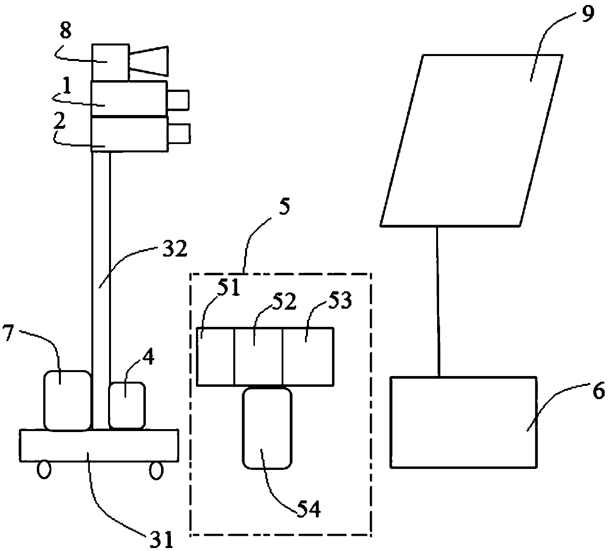
[0079] (1) In the absence of sunlight, use the visible light source module 8 to provide light to the surface of the solar module 9 to be tested, and adjust the three-axis adjustable mobile mechanical module, visible light imaging module 1 and infrared imaging through the control module 4 The position of the module 2 relative to the solar component 9 to be tested is such that the camera of the visible light imaging module 1 is perpendicular to the surface of the solar component 9 to be tested, and the visible light imaging module 1 is used to image the solar component 9 to be tested to obtain a picture of the solar component 9 to be tested;

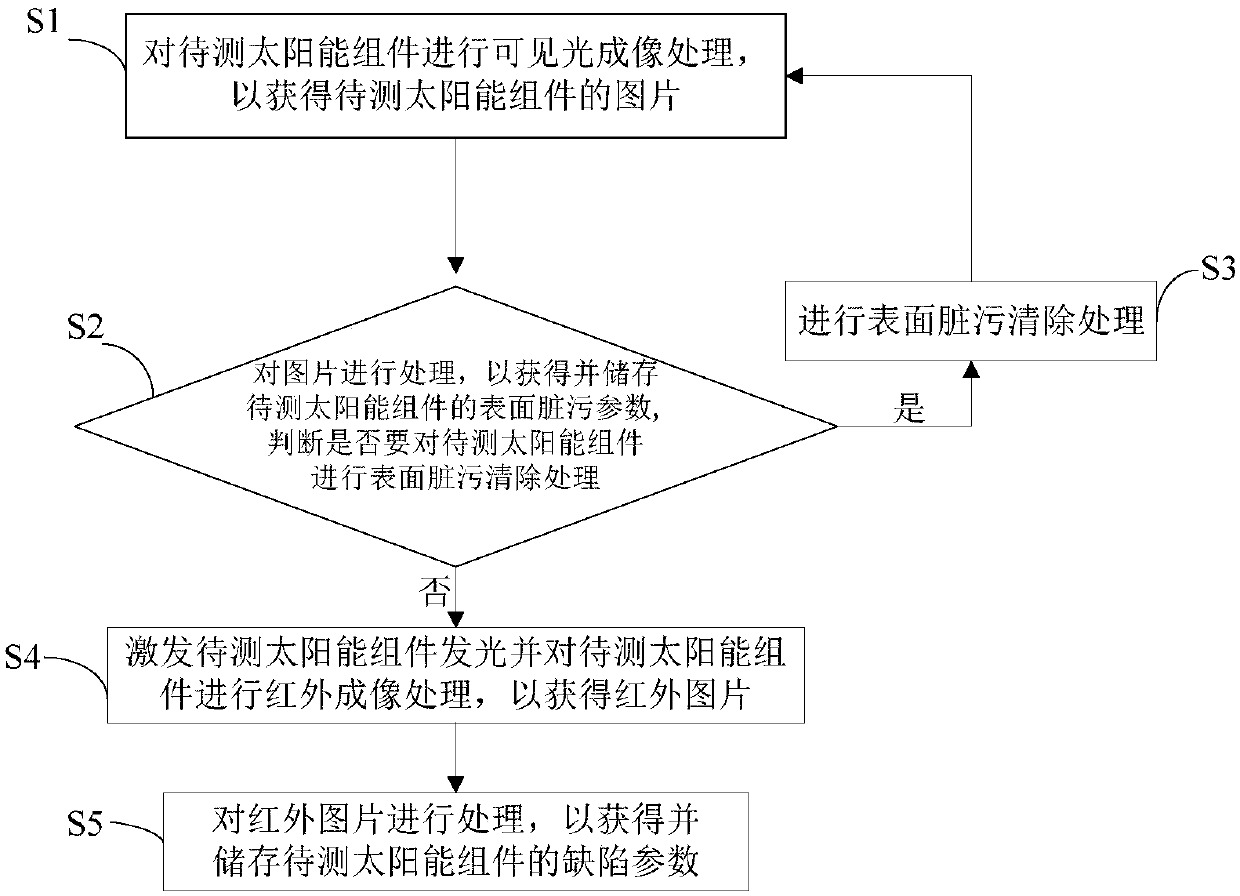
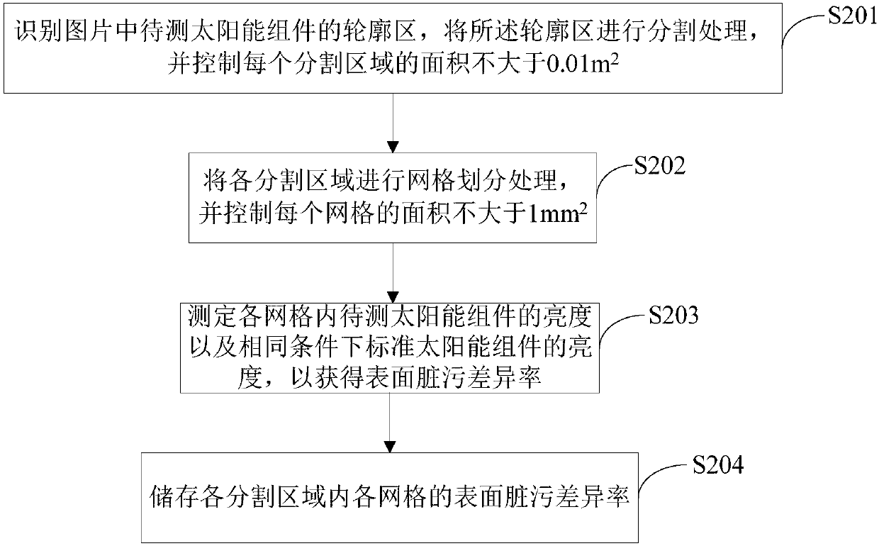
[0080] (2) Process the picture obtained in step (1) to obtain and store the surface dirt parameters of the solar module 9 to be tested, including:

[0081] (S1) The picture obtained in step (1) is transmitted to the picture analysis device 52 through the picture transmission device 51, and the outline area of ​​the solar module 9 to be test...


PUM


Abstract

The invention relates to the technical field of solar module fault detection and discloses a solar module fault detection system and method. The system comprises a visible light imaging module, an infrared imaging module, a three-axis adjustable movable mechanical module, a control module, a solar module luminous excitation module and a picture processing module, wherein the visible light imagingmodule and the infrared imaging module are both arranged on the three-axis adjustable movable mechanical module; the control module is connected with the three-axis adjustable movable mechanical module, the visible light imaging module and the infrared imaging module separately; the solar module luminous excitation module is used for being connected with a to-be-detected solar module during faultdetection; the picture processing module is connected with the visible light imaging module and the infrared imaging module separately. The method can be used for conveniently, flexibly and accuratelydetecting faults of the solar module.

Description

technical field [0001] The invention relates to the technical field of solar component fault detection, in particular to a solar component fault detection system and method. Background technique [0002] During the actual use of solar power generation systems such as distributed power stations, solar modules will be subjected to stresses such as hail, strong wind, rain and snow, temperature cycles, hot spots (hot spots caused by fallen leaves, dirt, etc.), vibration, etc. The lower solar modules are easy to cause damage and cause some faults and defects, which will lead to abnormal operation of the solar power generation system. If each solar module in the solar power generation system is disassembled separately and then tested separately, the workload will be huge. Therefore, it is very important to conveniently and quickly perform fault detection on the solar modules in operation of the solar power generation system without disassembling the solar modules. Contents of t...

Claims


Application Information

Patent Timeline
IPC IPC(8): G01N21/88G01N21/94
Inventor 王志强
Owner 东君新能源有限公司
Learn More