Eureka AIR delivers breakthrough ideas for toughest innovation challenges, trusted by R&D personnel around the world.

Efficient two-stage air compressor and control method thereof

An air compressor and two-stage compression technology, which is applied to mechanical equipment, machines/engines, liquid fuel engines, etc., can solve the problems of high cost of the two-stage screw host, high rated current of the motor, and large starting torque, etc., and achieves a simple structure , The effect of small screw force and low exhaust pressure

Inactive Publication Date: 2019-05-28
重庆奇螺流体设备有限公司
View PDF0 Cites 3 Cited by
  • Summary
  • Abstract
  • Description
  • Claims
  • Application Information

AI Technical Summary

Problems solved by technology

It mainly has the following problems: 1) adopts two hosts and two motors, and the cost is high
2) Due to the cooling and oil removal after the first stage of compression, the energy efficiency is high at full load; but correspondingly, the energy efficiency is low at full load, especially when the actual displacement is lower than 80% of the rated displacement
3) The system is complex and bulky
Although this kind of structure is small in size, there are still the following problems: 1) Because there are two pairs of rotor cavities and cooling cavities in the casing of the two-stage screw main engine, the structure is complex and the manufacturing requirements are high, resulting in the cost of the two-stage screw main engine. high
2) Because the two-stage screw host is driven by a motor, the rated current of the motor is large, and the power of the corresponding frequency converter is also large. The greater the power of the frequency converter, the higher the cost
3) Because one motor needs to drive two pairs of rotors through three gears at the same time, the starting torque is large

Method used

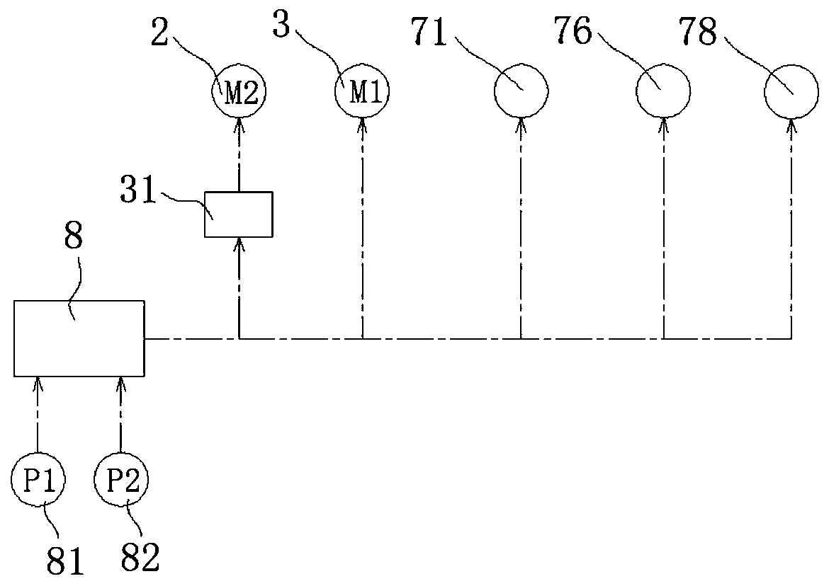

Image

  • Efficient two-stage air compressor and control method thereof
  • Efficient two-stage air compressor and control method thereof
  • Efficient two-stage air compressor and control method thereof

Examples


Embodiment 1

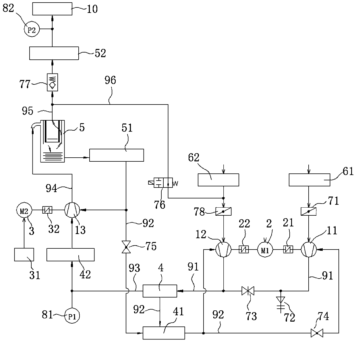
[0055] This embodiment is basically as figure 1 Shown: high-efficiency two-stage air compressor, including air intake system, three compressor hosts, primary oil-gas separation system, secondary oil-gas separation system, primary oil cooling system 41, secondary oil cooling system 51, primary air cooling system 42 and secondary air cooling system 52 .

[0056] The compression hosts are two primary compression hosts and a secondary compression host 13, both of which are screw compressors, and the two primary compression hosts are the first primary compression host 11 and the second primary compression host 12 respectively. The first-stage compression main engine 11 is connected to the first-stage motor 2 through the first coupling 21, and the first coupling 21 is a separate clamping type elastic coupling, so that the first-stage compression main engine 11 and the first-stage motor 2 Detachable connection. The first-stage motor 2 is a motor with dual output shafts, and the oth...

Embodiment 2

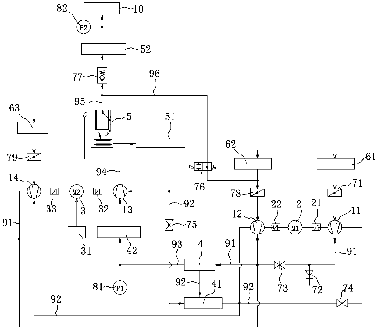
[0080] The difference between this embodiment and Embodiment 1 is: there are three primary compression hosts in this embodiment, such as image 3 As shown, in addition to setting the first-stage compression host 11 and the second-stage compression host 12 in Embodiment 1, a third-stage compression host 14 is also provided. In this embodiment, the second-stage motor 3 is a dual-output shaft frequency conversion motor, one output shaft is connected with the second-stage compressor host 13, and the other output shaft is detachably connected with the third-stage compressor host 14. Specifically, the third one can be made through the fourth shaft coupling 33 or a belt transmission mechanism. The primary compressor 14 is detachably connected to the secondary motor 3; thus the secondary motor 3 simultaneously drives the secondary compressor 13 and the third primary compressor 14 to rotate to compress air.

[0081] The air inlet of the third-stage compressor host 14 is also connected ...

Embodiment 3

[0085] The difference between this embodiment and the above two embodiments is that there are two first-level compression hosts in this embodiment, which are the second-level compression host 12 and the third-level compression host 14, wherein the second level The main compressor 12 is connected to the first-stage motor 2 through the second coupling 22 , and the third-stage main compressor 14 is connected to the other output shaft of the second-stage motor 3 through the fourth coupling 33 . Its working process is the same as that of the above-mentioned embodiment, and will not be repeated here.


PUM


Abstract

The invention relates to the field of air compressors and discloses an efficient two-stage air compressor. The efficient two-stage air compressor comprises two or three first-stage compressing main machines and a second-stage compressing main machine. If the number of the first-stage compressing main machines is three, the two first-stage compressing main machines are driven by a first-stage motor, and the other first-stage compressing main machine and the second-stage compressing main machine are driven by a variable frequency second-stage motor. When the air compressor is started, the second-stage motor is started firstly, then the first-stage motor is started when the second-stage motor operates under a low frequency, the frequency of the second-stage motor is adjusted to the working operating frequency after the first-stage motor is started, and the starting current of the air compressor is small. The two or three first-stage compressing main machines are arranged, and the maximumdisplacement of the air compressor is two or three times that of an air compressor in the prior art; and in addition, the gas displacement adjusting range of the air compressor is made wide.

Description

technical field [0001] The invention relates to the field of air compressors, in particular to a high-efficiency two-stage air compressor and a control method thereof. Background technique [0002] Two-stage air compressors are mostly screw type, mainly in two forms: single-host air compressor and dual-host air compressor. [0003] For dual-host air compressors, a large-rotor compressor main engine driven by a motor through a coupling acts as a primary compressor, and a small-rotor compressor main engine driven by another motor through a coupling serves as a secondary compressor. After the primary compression is completed, it is discharged The oil-gas mixture is subjected to oil-gas separation and cooling, and then undergoes two-stage compression. After the two-stage compression is separated from oil and gas, it flows into the compressed air pipe network after cooling. It mainly has the following problems: 1) Two hosts and two motors are used, and the cost is high. 2) Due ...

Claims


Application Information

Patent Timeline
Patent Type & Authority Applications(China)
IPC IPC(8): F04C23/00F04C29/02F04C29/04F04C28/02F04C28/06F04C28/08F04C28/24
CPCF04C23/001F04C28/02F04C28/06F04C28/08F04C28/24F04C29/026F04C29/04
Inventor 王汝强彭代君
Owner 重庆奇螺流体设备有限公司
Why Eureka
Eureka Blog
Learn More