
A structural mode of urban underground comprehensive utility corridor

A technology for integrated pipe gallery and pipe gallery, applied in underwater structures, infrastructure engineering, construction, etc., can solve the problems of high transportation cost, large transportation space, large volume, etc., achieve strong heat dissipation effect, and enhance connection firmness , the effect of high structural stability

Active Publication Date: 2020-01-10
FUZHOU UNIV
View PDF1 Cites 2 Cited by
  • Summary
  • Abstract
  • Description
  • Claims
  • Application Information

AI Technical Summary

Problems solved by technology

[0005] As far as the above-mentioned prefabricated integrated pipe gallery is concerned, since the entire integrated pipe gallery is made of concrete, due to the existence of accommodating chambers inside, it leads to a large overall volume, which requires a large transportation space and high transportation costs

Method used


Image

  • A structural mode of urban underground comprehensive utility corridor
  • A structural mode of urban underground comprehensive utility corridor
  • A structural mode of urban underground comprehensive utility corridor

Examples


Embodiment 1

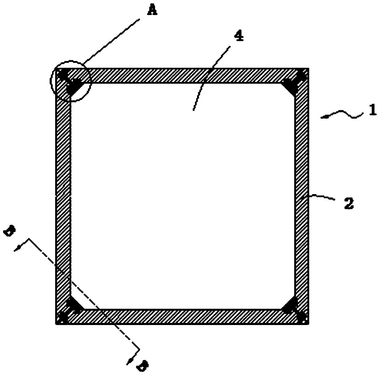
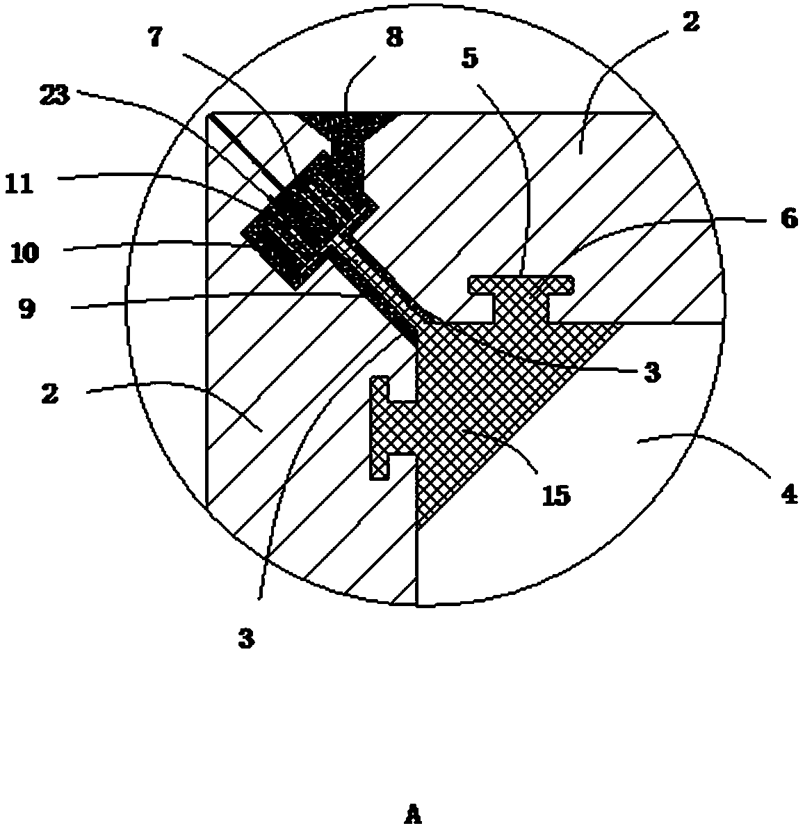
[0046] The structure of an urban underground comprehensive pipe gallery disclosed by the present invention includes a pipe gallery body 1, and the pipe gallery body 1 includes at least three pipe gallery side panels 2. In this embodiment, the pipe gallery body 1 on each The number of gallery side panels 2 is four pieces, and the shape of each tube gallery side panel 2 is a square plate. The tubular structure of the chamber 4, the inner space of the accommodating chamber 4 in the pipe gallery body 1 is a square channel.

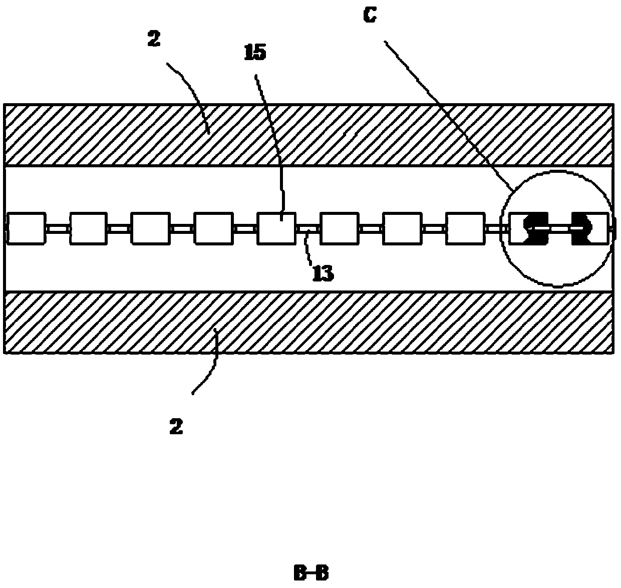
[0047] A number of connection blocks 15 are arranged in the accommodation chamber 4 in the pipe gallery body 1. The edge of the adjacent two pipe gallery side panels 2 is the conflicting side 3, and the connection blocks 15 are respectively distributed on the four sides of the pipe gallery body 1. On the corner, a T-shaped chute 5 is provided on the inner wall of the pipe gallery side plate 2 close to the accommodation chamber 4, and the length direction of th...

Embodiment 2

[0055] The number of pipe gallery bodies 1 in this embodiment is at least two, and each pipe gallery body 1 adopts the pipe gallery body 1 structure in Embodiment 1. All pipe gallery bodies 1 are arranged horizontally and parallel to each other, and two adjacent pipe gallery bodies The side plate 2 of the pipe gallery opposite to the gallery body 1 is a cooling plate surface 16, and a cooling gap 17 is left between two adjacent cooling plate surfaces 16; the side plates 2 of the pipe gallery on two adjacent pipe gallery bodies 1 are respectively the second One side plate 19, the second side plate 21, the first side plate 19 is provided with some first slide blocks 20, the second side plate 21 is provided with some second chute 22, the length direction of the second chute 22 is In the vertical direction, several second chute 22 are evenly distributed along the length direction of the pipe gallery body 1 , and the first slider 20 and the second chute 22 are slidably matched one b...


PUM


Abstract

The invention relates to a structural mode of an urban underground comprehensive pipe rack. The structural mode comprises a pipe rack body, and is characterized in that the pipe rack body comprises atleast three pipe rack side plates; the edges of two adjacent pipe rack side plates resist against each other to encircle a pipe-type structure with a receiving cavity; the structural mode further comprises a connection block; the resisting edges of two adjacent pipe rack side plates are resisting edges; T-shaped sliding chutes are formed in the inner walls, close to the receiving cavity, of the pipe rack side plates; the lengthwise directions of the T-shaped sliding chutes are consistent with the lengthwise directions of the pipe rack bodies; at least two T-shaped sliding blocks respectivelymatched with the T-shaped sliding chutes of two adjacent pipe rack side plates in a sliding manner are arranged on the connection block. The pipe rack of the above assembled structure can transport more pipe rack body components at one time under the condition of guaranteeing the stability of the entire assembled structure, and the transportation cost is also effectively controlled.

Description

technical field [0001] The invention relates to the technical field of pipe galleries, in particular to a structural mode of urban underground comprehensive pipe galleries. Background technique [0002] Comprehensive pipe gallery is the comprehensive corridor of underground urban pipelines, that is, to build a tunnel space underground in the city, integrating various engineering pipelines such as power, communication, gas, heating, water supply and drainage, etc., with special inspection ports and hoisting ports And monitoring system, the implementation of unified planning, unified design, unified construction and management, is an important infrastructure to ensure the operation of the city. [0003] Existing comprehensive pipe gallery structure is the Chinese invention patent of CN109056791A as the announcement number, in combination with its attached figure 1 , its structure mainly includes a pipe gallery, which is generally buried underground, and a containment chamber ...

Claims


Application Information

Patent Timeline
Patent Type & Authority Patents(China)
IPC IPC(8): E02D29/045
Inventor 庞胜华
Owner FUZHOU UNIV
Learn More