
Posterior lumbar interbody fusion system

A posterior and intervertebral technology, applied in the field of posterior lumbar auxiliary devices, can solve problems such as failure, screw loosening, and aggravating surgical trauma, and achieve the effects of avoiding complications, avoiding risks, and reducing treatment costs.

Pending Publication Date: 2019-05-28
XIAN HONGHUI HOSPITAL
View PDF0 Cites 2 Cited by
  • Summary
  • Abstract
  • Description
  • Claims
  • Application Information

AI Technical Summary

Problems solved by technology

In recent decades of clinical practice, the three surgical methods have achieved good clinical efficacy; however, all three surgical methods require pedicle screw fixation after intervertebral bone grafting and implantation of intervertebral fusion cages. This not only aggravates the trauma of the operation, but also may cause related complications such as screw loosening and failure, and the most important disadvantage is that patients often need to wait for a second operation to remove the pedicle screw after the intervertebral fusion is good.

Method used


Image

  • Posterior lumbar interbody fusion system
  • Posterior lumbar interbody fusion system
  • Posterior lumbar interbody fusion system

Examples


Embodiment 1

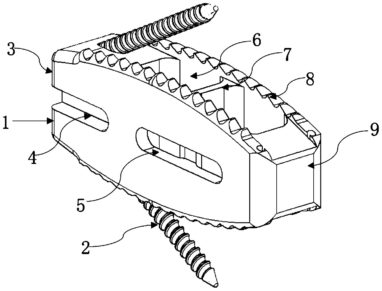
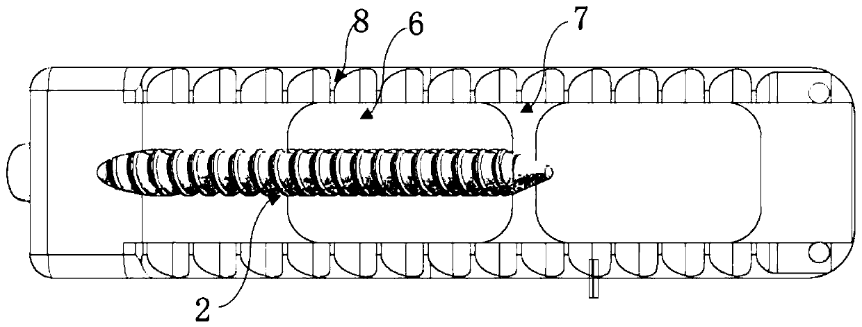
[0028] Such as Figure 1 to Figure 3 As shown, a posterior lumbar intervertebral fusion system of the present invention includes a cage body 1 and screws 2; the cage body 1 is an integrated structure with a shuttle-like appearance. The fusion device main body 1 includes a fusion device front end 9 and a fusion device end 3 in a bullet structure, and a bone graft cavity 6 penetrating up and down is formed on the fusion device main body 1 between the fusion device front end 9 and the fusion device end 3. The upper and lower surfaces of the fuser main body 1 are uniformly provided with a plurality of anti-slip protrusions; the tips of at least two screws 2 protrude obliquely from the upper and lower surfaces of the end 3 of the fusion cage respectively.

[0029] Wherein, the anti-slip convex body is a barb 8 or a protrusion with a tip, and the tip of the barb 8 is inclined to the end 3 of the fusion device, thereby realizing one-time fixation of the fusion device 1 . The bone gr...

Embodiment 2

[0037] Such as Figure 4 to Figure 6 As shown, a posterior lumbar intervertebral fusion system of the present invention includes a fusion device body 1 and screws 2; the fusion device body 1 is an integral structure with an arc-shaped appearance (approximately "kidney shape"). The fusion device main body 1 includes a fusion device front end 9 and a fusion device end 3 in a bullet structure, and a bone graft cavity 6 penetrating up and down is formed on the fusion device main body 1 between the fusion device front end 9 and the fusion device end 3. The upper and lower surfaces of the fuser main body 1 are uniformly provided with a plurality of anti-slip protrusions; the tips of at least two screws 2 protrude obliquely from the upper and lower surfaces of the end 3 of the fusion cage respectively.

[0038] Wherein, the anti-slip convex body is a pyramid.

[0039] Due to the curved structure of the "kidney-shaped" fusion device body 1, compared with the shuttle-shaped structure,...


PUM


Abstract

The invention discloses a posterior lumbar interbody fusion system which comprises a fusion cage body and screws, wherein the fusion cage body comprises a fusion cage front end and a fusion cage tailend; the fusion cage front end is of a bullet structure; a bone grafting cavity of which the upper part penetrates through the lower part is formed in the fusion cage body between the fusion cage front end and the fusion cage tail end; a plurality of antiskid convex bodies are uniformly arranged on each of the upper surface and the lower surface of the fusion cage body; and the tips of at least two screws respectively extend out of the upper surface and the lower surface of the fusion cage tail end obliquely. The posterior lumbar interbody fusion system for an operation can complete the fixation of an interbody fusion cage and an adjacent vertebral body well without the need of a pedicle screw and meets the treatment requirements of a novel operation way and achieves the treatment purposesof the novel operation way.

Description

technical field [0001] The invention belongs to the technical field of lumbar posterior auxiliary devices, in particular to a lumbar posterior intervertebral fusion system. Background technique [0002] Posterior lumbar decompression and interbody fusion is the most common surgical method for the treatment of lumbar disc herniation, lumbar spinal stenosis and other common lumbar diseases. Lumbar interbody fusion via Transforaminal Lumbar Interbody Fusion, TLIF, and Minimally Invasive Surgery——Transforaminal Lumbar Interbody Fusion, MIS-TLIF under minimally invasive access. In recent decades of clinical practice, the three surgical methods have achieved good clinical efficacy; however, all three surgical methods require pedicle screw fixation after intervertebral bone grafting and implantation of intervertebral fusion cages. This not only aggravates the trauma of the operation, but also may cause related complications such as screw loosening and failure, and the most importa...

Claims


Application Information

Patent Timeline
Patent Type & Authority Applications(China)
IPC IPC(8): A61F2/44A61F2/30
Inventor 王彪郝定均孔令擘贺宝荣郭华赵勤鹏张吉涛
Owner XIAN HONGHUI HOSPITAL
Learn More