Ecological planting system

A technology for ecological planting and planting racks, applied in control/regulation systems, renewable energy machines, botany equipment and methods, etc., can solve the problems of low automation level, single energy supply for planting greenhouses, etc., and achieve the effect of reducing labor costs

Inactive Publication Date: 2019-05-28
GUIZHOU SUOER TECH CO LTD
View PDF7 Cites 0 Cited by
  • Summary
  • Abstract
  • Description
  • Claims
  • Application Information

AI Technical Summary

Problems solved by technology

[0006] The purpose of the present invention is to provide an ecological planting system to solve the problems of single energy supply and low automation level in existing planting greenhouses

Method used


Image

  • Ecological planting system
  • Ecological planting system
  • Ecological planting system

Examples


Embodiment 1

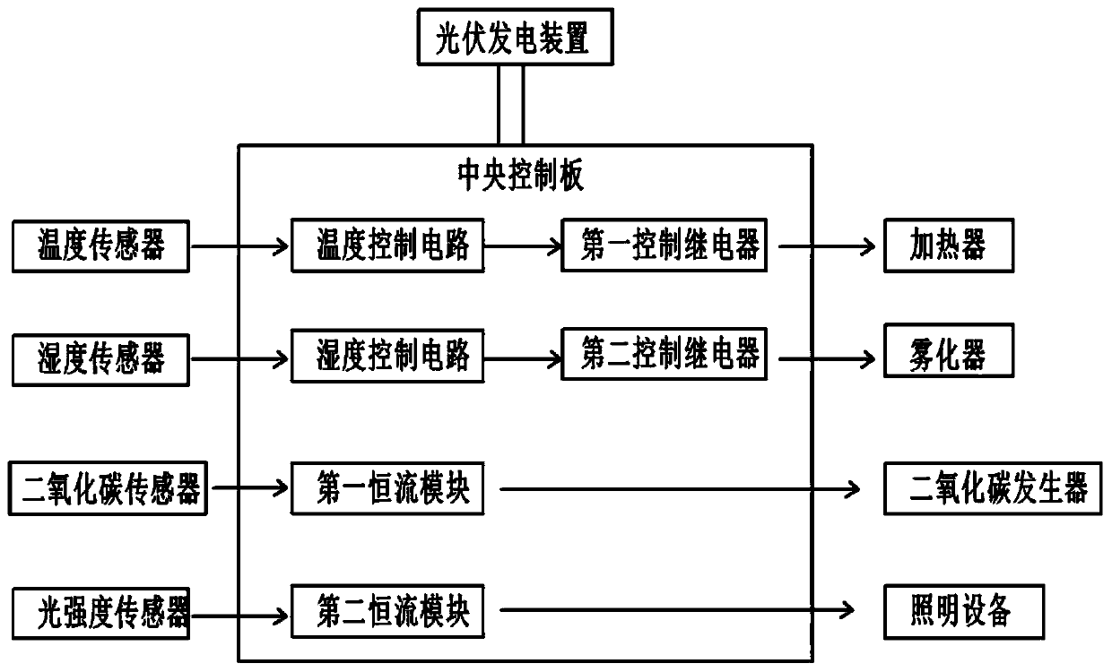
[0028] The embodiment is basically as attached figure 1 Shown: an ecological planting system with the following technical features (the technical features used in Example 1 are collectively referred to as features ①): including a planting house, in which there are multiple planting racks for planting plants. The ecological planting system also includes a photovoltaic power generation device and an intelligent control system. The photovoltaic power generation device is used to provide electrical energy for all electronic components in the intelligent control system. The intelligent control system includes a logic control device, as well as temperature sensors, humidity sensors, carbon dioxide sensors and light intensity sensors connected to the input ports of the logic control device, and temperature control equipment, atomizing pumps, and carbon dioxide generators connected to the output ports of the logic control device. And lighting equipment. The photovoltaic power generatio...

Embodiment 2

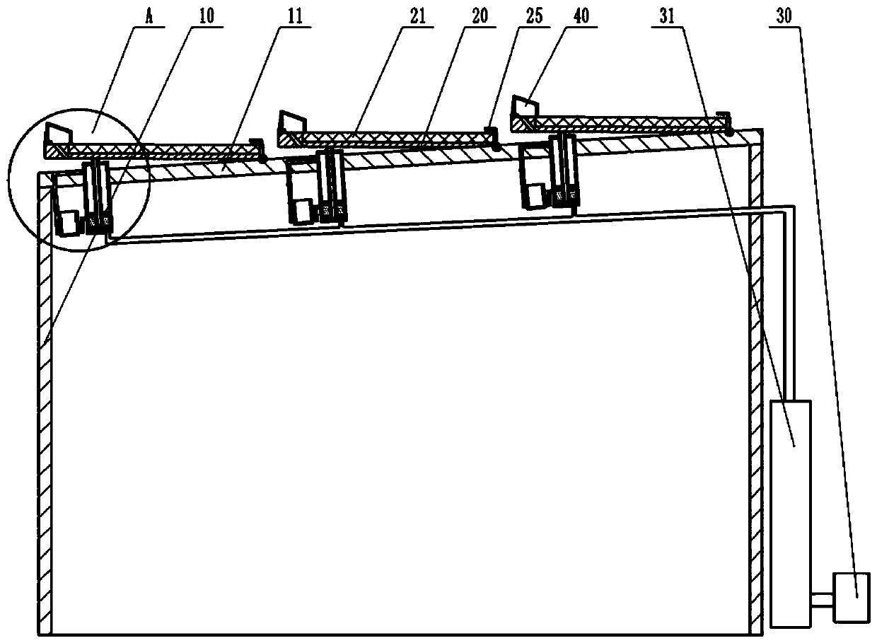
[0034] The difference between embodiment 2 and embodiment 1 is that it also includes the following technical features (all the new technical features in embodiment 2 are collectively referred to as features ②): figure 2 As shown, the planting house includes a canopy body 10 and a canopy 11 arranged above the canopy body 10. The canopy 11 is inclined to the left and downward, and the inclination angle is 10-20 degrees. In this embodiment, the inclination angle is set to 10 degrees. .

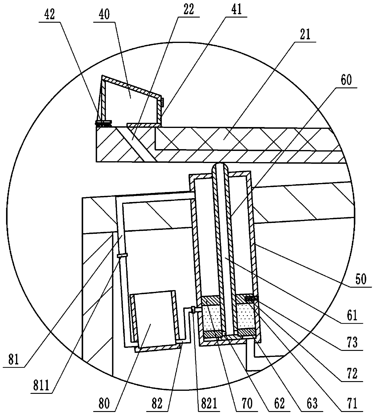
[0035] The roof 11 is provided with a plurality of mounting plates 20, the lower right end of the mounting plate 20 is hinged on the roof 11, the upper surface of the mounting plate 20 is provided with a mounting groove, the photovoltaic panel 21 is installed in the mounting groove, and the photovoltaic panel 21 is located in the mounting groove. When in the groove, the upper surface of the photovoltaic panel 21 is flush with the upper surface of the mounting board 20. Combine Figure 4 As shown, a...


PUM


Abstract

The invention belongs to the technical field of ecological agriculture, and particularly discloses an ecological planting system. The ecological planting system comprises a planting room, and furthercomprises a photovoltaic power generation system and an intelligent control system, whereinthe planting room is internally provided with a planting frame used for planting plants, the photovoltaic power generation system is used for providing electric energy for electronic components in the intelligent control system, the intelligent control system comprises a logic control device, a temperature sensor, a humidity sensor, a carbon dioxide sensor,a light intensity sensor, temperature control equipment, an atomizing pump, a carbon-dioxide generatorand lighting equipment, the temperature sensor,the humidity sensor, the carbon dioxide sensor and the light intensity sensor are respectively connected with the input port of the logic control device, and the temperature control equipment, the atomizing pump, the carbon-dioxide generator and the lighting equipment are respectively connected with the output port of the logic control device. The ecological planting system is used, and thus the problems that energy supply is single, automation level is low in an existing planting room can be solved.

Description

Technical field [0001] The invention belongs to the technical field of ecological agriculture, and particularly relates to an ecological planting system. Background technique [0002] Agriculture is the primary industry, and agriculture is the basic industry that supports the construction and development of the national economy. Planting is a specific type of agriculture that provides vegetables, fruits, Chinese medicinal materials and flowers for human life. The traditional planting industry faces many difficulties: the difficulties brought about by rapid population growth. According to population experts, the world's population will increase to 9 billion by 2050. At that time, it will be necessary to increase the land equivalent to an area close to China to feed the global population. The dilemma brought about by land reduction, relative to the rapidly increasing population, the world’s land has not increased but declined year by year. Because of global climate change, drought...

Claims


Application Information

Patent Timeline
IPC IPC(8): A01G9/18A01G9/24A01G7/04H02S20/20H02S40/10G05D27/02
CPCY02E10/50Y02P60/12Y02A40/25
Inventor 李小红
Owner GUIZHOU SUOER TECH CO LTD
Why Eureka
Try Eureka