Impurity rethreshing lifting trough

A technology for waste and trough transportation, which is applied in threshing equipment, application, agricultural machinery and implements, etc. It can solve the problems that affect the cleaning effect and complex structure, and achieve the effect of simple structure and convenient installation

Inactive Publication Date: 2019-05-24
朱洪建 +2
View PDF0 Cites 0 Cited by
  • Summary
  • Abstract
  • Description
  • Claims
  • Application Information

AI Technical Summary

Problems solved by technology

[0002] The existing rice and wheat combine harvester handles the waste (the grains and ear heads that have not been completely peeled, called the waste), most of which are rubbed by the re-extractor first, and then blown by the fan along the conveying tube. The cleaning room, or the auger sends the debris into the cleaning room, the structure is complex, and the wind blowing into the cleaning room affects the cleaning effect

Method used


Image

  • Impurity rethreshing lifting trough
  • Impurity rethreshing lifting trough

Examples


Embodiment Construction

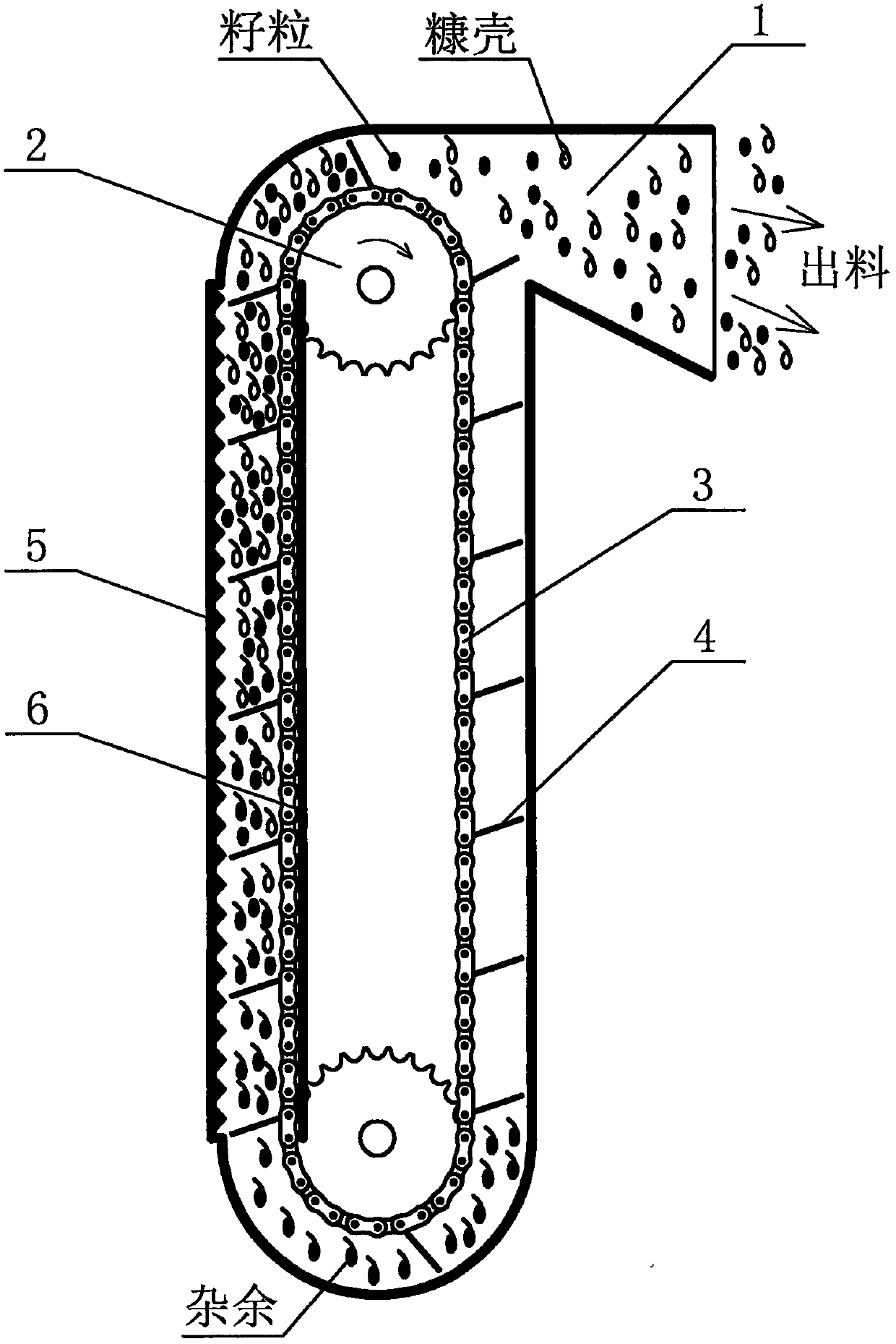
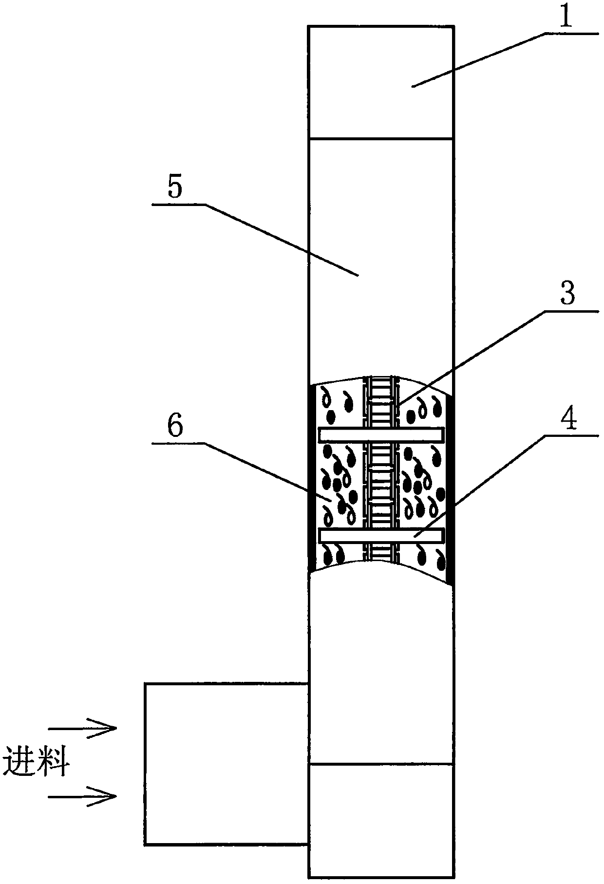
[0009] A kind of lifting tank for extra complex removal, which includes a lifting shell (1), a partition (6) that divides the lifting shell (1) into two sides, and sprockets (2) installed at the upper and lower ends of the lifting shell (1). ), the lifting chain (3) installed on the sprocket (2), the lifting bracket (4) fixed on the lifting chain (3), the washboard (5) fixed on the inner wall of the lifting shell (1) ).

[0010] The lifting bracket surface on the lifting chain is at an obtuse angle to the driving direction of the lifting chain.

[0011] The washboard on the inner wall of the lifting shell is fixed on the inner wall of the lifting shell on the side with a partition, which is conducive to rubbing the debris between the lifting bracket and the washboard.

[0012] The surface of the lifting bracket and the driving direction of the lifting chain form an obtuse angle. When the lifting chain is driven to the side where the washboard is installed, the driving directi...


PUM


Abstract

The invention provides an impurity rethreshing lifting trough for a rice and wheat combine harvester. The impurity rethreshing lifting trough comprises a lifting shell, a partition, sprocket wheels, alifting chain, a lifting board and a washboard, wherein the partition divides the lifting shell into two sides; sprocket wheels are mounted on both ends of the upper and lower ends of the lifting shell; the lifting chain is installed on the sprocket wheels; the lifting board is fixed on the lifting chain; the washboard is fixed on the inner wall of the lifting shell. The impurity rethreshing lifting trough has the advantages of being a rethreshing and lifting integrated device to solve the problems of the rethreshing and lifting, being capable of peeling the impurities and then sending the same to a cleaning room, and being simple in structure.

Description

technical field [0001] The invention belongs to the technical field of agricultural machinery, and relates to a waste recovery lifting device for a rice-wheat combine harvester. Background technique [0002] The existing rice and wheat combine harvester handles the waste (the grains and ear heads that have not been completely peeled, called the waste), most of which are rubbed by the re-extractor first, and then blown by the fan along the conveying tube. The cleaning room, or the miscellaneous materials are sent into the cleaning room by the auger, has a complex structure, and the wind blowing into the cleaning room affects the cleaning effect. Contents of the invention [0003] The purpose of the present invention is to provide a device that integrates re-extraction and lifting to solve the problem of re-extraction and lifting, so that the impurities can be rubbed with the washboard installed on the inner wall of the lifting shell during the lifting process, so that the i...

Claims


Application Information

Patent Timeline
Patent Type & Authority Applications(China)
IPC IPC(8): A01F12/18
Inventor 朱洪建马转红朱琳琳
Owner 朱洪建
Why Eureka
Try Eureka