


Quick Research
Generate reliable direction feasibility study reports for your R&D in just a few steps.

Technical Q&A
Discover and master advanced knowledge NOW. Basics, ideas, possibilities, all at once.

Find Solutions
As an expert in R&D theories, this can generate solutions to your technical problems instantly.

Evaluate Feasibility
Analyze your overall solution with one click, know your potential R&D risks in advance.

Monitor Landscape
Get weekly tech updates, stay abreast of the latest tech innovations and key insights.
Tire curing mold
一种轮胎硫化模具、轮胎的技术,应用在胎、家里用具、其他家里用具等方向,能够解决成型不良、空气滞留等问题,达到抑制成型不良的效果
- Summary
- Abstract
- Description
- Claims
- Application Information
AI Technical Summary
Problems solved by technology
Method used
Image

Examples
no. 1 Embodiment approach
[0032] Hereinafter, a first embodiment will be described with reference to the drawings.
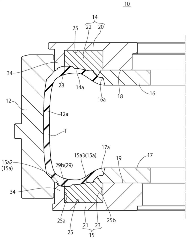
[0033] figure 1 It is a sectional view of the tire vulcanizing mold 10 according to this embodiment. The tire vulcanization mold 10 is a molding mold for vulcanizing and molding an unvulcanized raw tire T arranged with the tire axial direction as the vertical direction by heating and pressurizing, and includes a tread mold 12, a pair of upper and lower tire tires Side molds 14, 15, a pair of upper and lower bead rings 16, 17.
[0034] The tread mold 12 is a mold having a tread molding surface 12 a for molding a tread portion of a tire. The tread mold 12 is composed of a plurality of sectors divided in the tire circumferential direction. The plurality of sectors are provided so as to be capable of scaling and displacing along the radial direction of the tire (tire radial direction). In the mold-closed state in which the segments are arranged at the mold-closing position, the segments ...
no. 2 Embodiment approach
[0067] based on Figure 9 as well as Figure 10 A second embodiment of the present invention will be described. In addition, the same code|symbol is attached|subjected to the same structure as 1st Embodiment mentioned above, and detailed description is abbreviate|omitted.
[0068] In the above-mentioned first embodiment, although the end portions of the first gap 29a and the second gap 29b formed between the sidewall mold main body 21 and the mold block 23 on the sidewall molding surface 15 side are formed so that air can pass through But unvulcanized rubber will not penetrate to this degree of size, but as Figure 9 as well as Figure 10 As shown, the groove 30 having a width larger than that of the first gap 29a may be provided on the sidewall molding surface 15a so as to overlap the first gap 29a. The groove 30 is also called a sawcut or a serration, and is, for example, a fine groove whose cross-sectional shape is a triangular shape that becomes narrower as it goes dow...
no. 3 Embodiment approach
[0073] based on Figure 11 as well as Figure 12 A third embodiment of the present invention will be described. In addition, the same code|symbol is attached|subjected to the same structure as the above-mentioned 1st and 2nd embodiment, and detailed description is abbreviate|omitted.
[0074] In the present embodiment, a plurality of grooves 32 extending parallel to the gap 29 are provided on the sidewall molding surface 15 a near the gap 29 formed between the sidewall mold body 21 and the mold block 23 . The plurality of dimples 32 are provided in parallel to each other on at least a part of the sidewall forming surface 15a to form a linear decorative pattern on the sidewall portion of the tire. In the present embodiment, the plurality of grooves 32 are provided in parallel to the first gap 29 a formed between the radially inner wall surface 25 c of the concave portion 25 and the side wall 23 a of the die block 23 .
[0075] According to the present embodiment, since the g...
PUM
| Property | Measurement | Unit |
|---|---|---|
| radius | aaaaa | aaaaa |
Abstract
Description
Claims
Application Information
 - R&D Engineer
- R&D Manager
- IP Professional
- Industry Leading Data Capabilities
- Powerful AI technology
- Patent DNA Extraction
Browse by: Latest US Patents, China's latest patents, Technical Efficacy Thesaurus, Application Domain, Technology Topic, Popular Technical Reports.
© 2024 PatSnap. All rights reserved.Legal|Privacy policy|Modern Slavery Act Transparency Statement|Sitemap|About US| Contact US: help@patsnap.com