Failure monitoring system and method of engine intake electronic decompression valve

A failure monitoring and engine technology, which is applied in the direction of engine components, machines/engines, mechanical equipment, etc., can solve problems such as single factors, limited use range, complex calculations, etc.

Active Publication Date: 2019-05-21
DONGFENG MOTOR CORP HUBEI
View PDF11 Cites 4 Cited by
  • Summary
  • Abstract
  • Description
  • Claims
  • Application Information

AI Technical Summary

Problems solved by technology

[0003] CN201610017939.8, Fault diagnosis system and diagnostic method for blockage of engine intake pressure relief valve, the technical solution of the invention determines whether blockage occurs by monitoring the number of alternating positive and negative gradients of the boost pressure change rate, and the calculation is relatively complicated; CN201511031886. 7. A control method for preventing turbocharger surge. The technical solution patent of this invention is to limit the minimum flow rate of the throttle valve to avoid s

Method used


Image

  • Failure monitoring system and method of engine intake electronic decompression valve
  • Failure monitoring system and method of engine intake electronic decompression valve
  • Failure monitoring system and method of engine intake electronic decompression valve

Examples


Embodiment 1

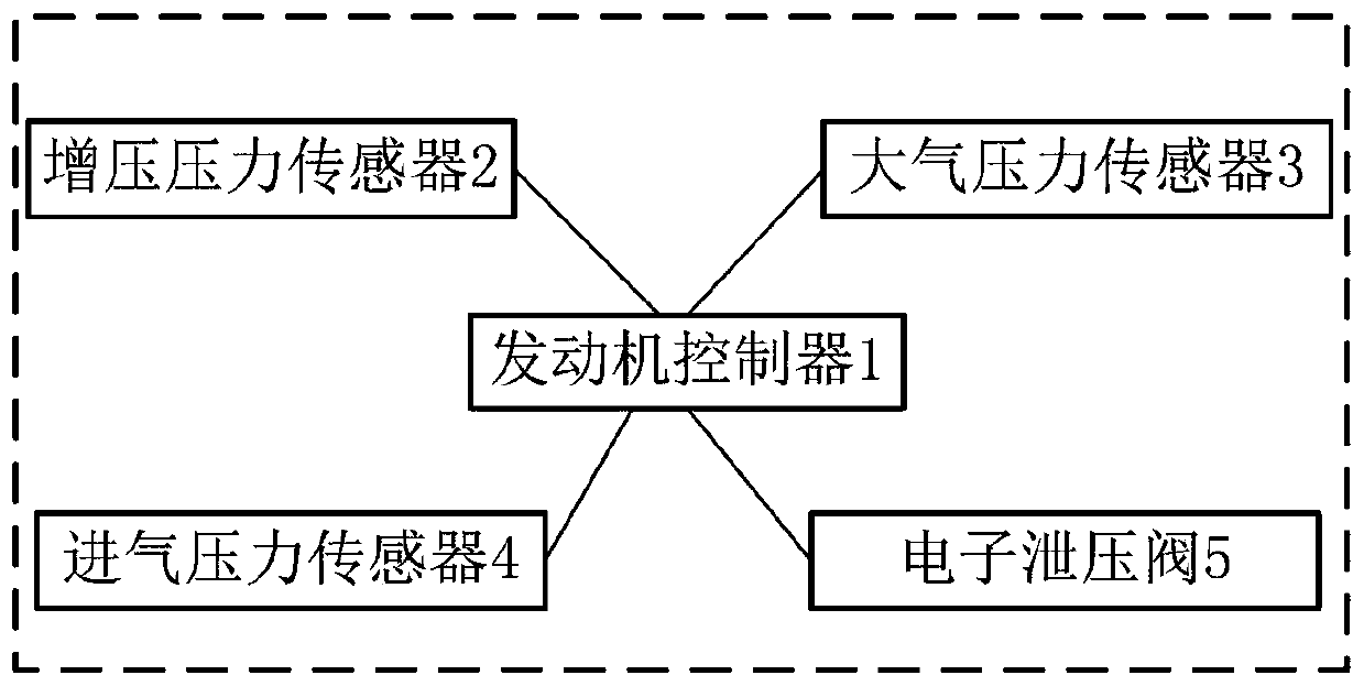
[0084] like figure 1 As shown, a failure monitoring system for an engine intake electronic pressure relief valve includes an engine controller 1 , a boost pressure sensor 2 , an atmospheric pressure sensor 3 , an intake pressure sensor 4 , and an electronic pressure relief valve 5 .

[0085] The engine controller 1 is the Engine Management System, referred to as EMS.

[0086] The boost pressure sensor 2 is arranged behind the engine intake compressor, used to detect the gas pressure at the outlet of the engine intake compressor, and is connected with the engine controller.

[0087] The atmospheric pressure sensor 3 is used to detect the atmospheric pressure and is connected with the engine controller.

[0088] The intake air pressure sensor 4 is arranged behind the throttle valve, is used for detecting the gas pressure behind the throttle valve, and is connected with the engine controller.

[0089] The electronic pressure relief valve 5 is used to guide the airflow to the fr...

Embodiment 2

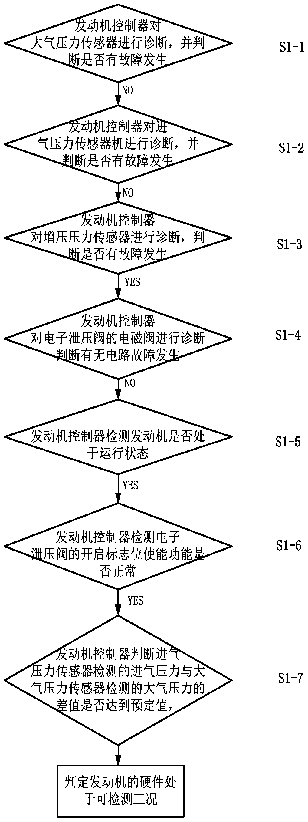
[0108] image 3 is a sub-step schematic diagram of step S1 in the embodiment of the present invention.

[0109] On the basis of Embodiment 1, this embodiment further optimizes the detection method of whether the engine is in a detectable working condition, specifically including:

[0110] Step S1-1, the engine controller diagnoses the atmospheric pressure sensor and judges whether there is a fault, if not, proceed to the next step;

[0111] Step S1-2, the engine controller diagnoses the intake pressure sensor, and further judges whether there is a fault, if not, proceed to the next step;

[0112] Step S1-3, the engine controller diagnoses the boost pressure sensor, and further judges whether there is a fault, and if so, proceed to the next step;

[0113] Step S1-4, the engine controller diagnoses the solenoid valve of the electronic pressure relief valve, and judges whether there is a circuit fault, and if not, proceed to the next step;

[0114] Step S1-5, the engine contro...

Embodiment 3

[0119] On the basis of Embodiment 1, this embodiment further optimizes the detection method of whether the engine is in a detectable working condition, when the following conditions are all satisfied:

[0120] The engine controller diagnoses the atmospheric pressure sensor, and no fault occurs;

[0121] The engine controller diagnoses the intake air pressure sensor, and no fault occurs;

[0122] The engine controller diagnoses the boost pressure sensor, and a fault occurs;

[0123] The engine controller diagnoses the solenoid valve of the electronic pressure relief valve, and no circuit failure occurs;

[0124] The engine controller detects that the engine is running;

[0125] The engine controller detects that the enable function of the open flag of the electronic pressure relief valve is normal;

[0126] The engine controller judges that the difference between the intake air pressure detected by the intake pressure sensor and the atmospheric pressure detected by the atmos...


PUM


Abstract

The invention discloses a failure monitoring system of an engine intake electronic decompression valve. The system comprises an engine controller, a boost pressure sensor, an atmospheric pressure sensor, an intake pressure sensor and the electronic decompression valve. An engine controller operation detection method comprises the steps of first, judging whether hardware of an engine is in the detectable working condition or not, and entering the second step if yes; second, carrying out first-order low-pass filtering processing on the actual boost pressure signals to obtain the boost pressure signal difference; third, carrying out self summation on the boost pressure signal difference within time t to obtain the total value of the boost pressure signal difference; fourth, judging whether the summation time is larger than the calibration value or not, returning to the third step if not, and entering the fifth step if yes; fifth, judging whether the total value of the boost pressure signal difference is larger than the calibration value or not, returning the failure number to zero and entering the first step if not, and entering the sixth step if yes; and sixth, accumulating the failure number and judging whether the failure number is larger than the calibration value, if not, determining that the electronic decompression valve is normal, and if yes, determining that the electronic decompression valve fails, and entering the first step.

Description

technical field [0001] The patent of the present invention relates to the field of engine control, in particular to a failure monitoring system and method for an engine intake electronic pressure relief valve. Background technique [0002] When the torque of the supercharged engine is reduced such as loose throttle or engine shutdown, in response to the torque reduction request, the throttle valve will be closed quickly to reduce the intake air volume to achieve the effect of torque reduction. The throttle valve is closed quickly, the pressure relief valve is opened, and when the gas flows through the pressure relief valve, if the pressure relief valve is not opened normally, the air flow oscillates back and forth between the front end of the throttle valve and the middle pipe at the rear end of the compressor, resulting in surge. If this phenomenon continues for a period of time, it will seriously affect drivability, pressure relief valve life and NVH (English abbreviation ...

Claims


Application Information

Patent Timeline
IPC IPC(8): F02B39/16F04D27/02
Inventor 秦龙杨柳春刘磊陈中天
Owner DONGFENG MOTOR CORP HUBEI
Why Eureka
Try Eureka