Rubber ring lifter

A hoist and apron technology, applied in the direction of conveyors, conveyor objects, transportation and packaging, etc., can solve the problems of inconvenient roller pressing and overlapping of aprons

Inactive Publication Date: 2019-05-21
珠海市明明机器人科技有限公司
View PDF14 Cites 2 Cited by
  • Summary
  • Abstract
  • Description
  • Claims
  • Application Information

AI Technical Summary

Problems solved by technology

Therefore, the conveying mechanism is generally used to transport the apron to the material receiving table of the roller press machine, but the existing conveying mechanism often has the phenomenon of overlapping the apron during the process of conveying the apron, which brings new problems for the subsequent roller press. inconvenient

Method used


Image

  • Rubber ring lifter
  • Rubber ring lifter
  • Rubber ring lifter

Examples


Embodiment Construction

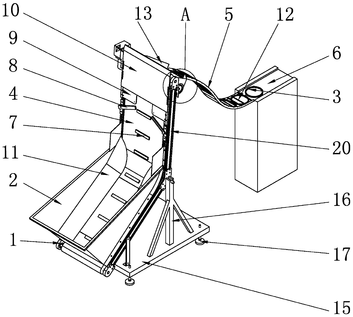
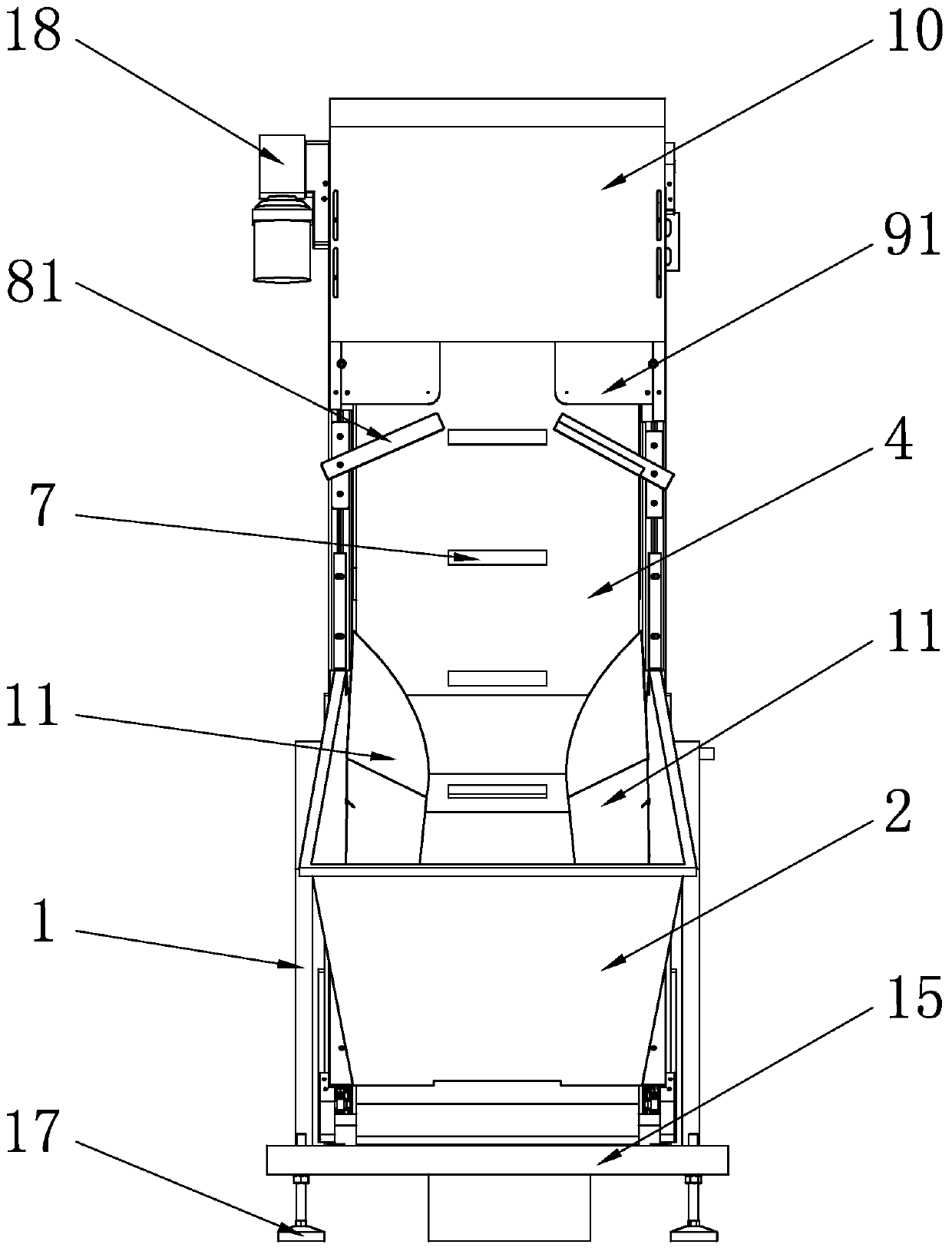
[0022] see figure 1 with image 3 , a kind of apron lifter of the present invention, comprises frame 1 and the vertical board 20 that is arranged on frame 1 and hopper 2, can place several rubber rings 3 in described hopper 2, the bottom of described hopper 2 and vertical board 20 is provided with conveyor belt 4, and described conveyor belt 4 is driven by motor 18, and the output end of described conveyor belt 4 is connected with receiving platform 6 through slideway 5, and the output end of described conveyor belt 4 is arranged on stand plate 20 and Higher than the hopper 2, the conveyor belt 4 is provided with several lifting plates 7 along the conveying direction, and the distance between two adjacent lifting plates 7 is greater than the width of one apron and less than the width of two aprons. Height-limiting part 8 and width-limiting part 9, described height-limiting part 8 and width-limiting part 9 are all arranged on the top of conveyer belt 4, and described height-li...


PUM


Abstract

The invention discloses a rubber ring lifter. The rubber ring lifter comprises a rack and further comprises a vertical plate and a hopper which are arranged on the rack; a plurality of rubber rings can be placed in the hopper; the bottom of the hopper and the vertical plate are provided with a conveyor belt, and the output end of the conveyor belt is connected with a receiving table through a sliding way and arranged on the vertical plate, and is higher than the hopper; the conveyor belt is provided with a plurality of lifting plates, and the space between every two adjacent lifting plates islarger than the width of one rubber ring and smaller than the width of the two corresponding rubber rings; a height limiting piece and a width limiting piece are arranged on the vertical plate and both arranged above the conveyor belt; and the height limiting piece and the width limiting piece limit passing of the rubber rings in the direction perpendicular to the output end of the conveyor belt and the width direction of the conveyor belt correspondingly, thus the rubber rings are conveyed to the sliding way through the conveyor belt one by one, and also slide down to the receiving table fromthe sliding way one by one, the rubber ring stacking phenomenon is avoided, subsequent assembling is convenient, the conveying efficiency is high, noise is small, and the cost is low.

Description

technical field [0001] The invention relates to the technical field of microwave oven assembly, in particular to an apron hoist. Background technique [0002] With the rapid development of the home appliance industry, the use of microwave ovens has become more and more widespread, so the assembly and production of microwave ovens needs to be more efficient. The rotating wheel placed in the microwave oven is an important component to ensure that the microwave can heat food evenly. It is composed of an apron and a roller. Generally, there are three legs on an apron, and a roller is installed on each leg. Now, generally, the roller is pressed onto the apron with a roller press machine. Therefore, the conveying mechanism is generally used to transport the apron to the material receiving table of the roller press machine, but the existing conveying mechanism often has the phenomenon of overlapping the apron during the process of conveying the apron, which brings new problems for...

Claims


Application Information

Patent Timeline
IPC IPC(8): B65G15/00B65G21/20B65G47/34
Inventor 刘春华宋超刚白明
Owner 珠海市明明机器人科技有限公司
Why Eureka
Try Eureka