
Automatic cleaning device for fiber cutter

An automatic cleaning and cutter technology, applied in the direction of using liquid cleaning methods, chemical instruments and methods, cleaning methods and utensils, etc., can solve the problems of spending 40-60 minutes, delaying construction efficiency, etc., to achieve convenient use and operation, reduce The effect of reasonable labor intensity and structural composition

Pending Publication Date: 2019-05-21
ZHEJIANG MEITONG ROAD CONSTR MACHINERY
View PDF9 Cites 0 Cited by
  • Summary
  • Abstract
  • Description
  • Claims
  • Application Information

AI Technical Summary

Problems solved by technology

The number of fiber cutters is large, and each vehicle is generally designed to have 24 to 32 pieces. It takes 40-60 minutes to clean each time, which delays construction efficiency

Method used


Image

  • Automatic cleaning device for fiber cutter

Examples


Embodiment Construction

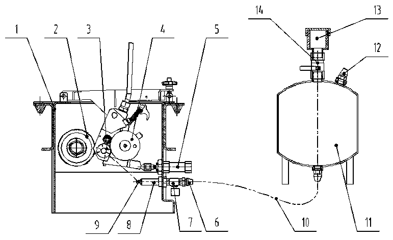
[0010] The present invention will be described in detail below in conjunction with accompanying drawing: figure 1 As shown, an automatic cleaning device for a fiber cutter according to the present invention, the fiber cutter includes a fiber cutting bin 1 equipped with one or more fiber cutter assemblies, and the fiber cutting bin 1 It includes an thimble cylinder 5 capable of ejecting the fiber cutter assembly, and a driving steel wheel 2 that drives the blade holder 3 to rotate. For fiber filaments, the automatic cleaning device includes an oil tank 11 that can be filled with cleaning liquid, and the oil tank 11 is connected to the narrow-angle nozzle 9 built in the fiber cutting bin 1 through a high-pressure oil pipe 10 and an electromagnetic ball valve 7 , the narrow-angle nozzle 9 is facing the blade frame 3 and the driven rubber wheel 4.

[0011] As shown in the figure: the narrow-angle nozzle 9 is connected to a transition joint 8 fixed in the fiber cutting chamber 1, ...


PUM


Abstract

The invention discloses an automatic cleaning device for a fiber cutter. The fiber cutter comprises a fiber cutting bin provided with one or more fiber cutter assemblies. A centre air cylinder capableof jacking the fiber cutter assemblies out and a driving steel wheel driving a blade frame to rotate are included in the fiber cutting bin, wherein fiber filaments dragged out and cut off are arranged between the blade frame and a driven rubber wheel. The automatic cleaning device comprises an oil tank capable of being filled with cleaning liquid, and the oil tank is connected with a narrow-anglenozzle through a high-pressure oil pipe and an electromagnetic ball valve, wherein the narrow-angle nozzle is arranged in the fiber cutting bin and is right opposite to the blade frame and the drivenrubber wheel. The automatic cleaning device has the characteristics that structure composition is reasonable, usage and operation are convenient, the labor intensity of operators can be lowered, andthe equipment construction efficiency and construction quality are improved.

Description

technical field [0001] The invention relates to an automatic cleaning device for a fiber cutter, which is mainly used for road machinery such as fiber synchronous sealing vehicles and slurry sealing vehicles, and belongs to the technical field of mechanical equipment. Background technique [0002] With the continuous increase of highway mileage in our country, the construction and maintenance of the road surface have also received special attention. Various new technologies for pavement maintenance and construction have been widely promoted and applied. The fiber sealing layer has a unique network winding structure. Due to the high tensile strength of the fiber itself, the tensile, shearing, compressive and impact strength of the sealing layer are effectively improved. The unique structure of the fiber seal layer has high tension and elasticity, and has a strong absorption and dispersion function for stress, which can effectively inhibit the occurrence of reflective cracks,...

Claims


Application Information

Patent Timeline
Patent Type & Authority Applications(China)
IPC IPC(8): B08B3/02E01C19/05
Inventor 房本地
Owner ZHEJIANG MEITONG ROAD CONSTR MACHINERY
Learn More