
Battery shock absorber of new energy automobile

A new energy vehicle and battery technology, which is applied in the direction of secondary batteries, battery covers/end covers, battery pack components, etc., can solve the problems of reduced battery life, heat dissipation, and reduced shock absorption effect, etc., to achieve extended The effect of improving the service life, improving the shock absorption effect, and improving the heat dissipation effect

Inactive Publication Date: 2019-05-17
NANJING LINGYA AUTOMOBILE TECH RES INST
View PDF5 Cites 6 Cited by
  • Summary
  • Abstract
  • Description
  • Claims
  • Application Information

AI Technical Summary

Problems solved by technology

[0002] The car will vibrate during operation, and the battery installed on the car will also vibrate. The battery shock absorber can prevent the battery from vibrating and prolong the service life of the battery; the existing car shock absorber has certain disadvantages in use. The shock absorbing spring is only installed on the side wall, which reduces the shock absorbing effect, and the battery is in a relatively closed space, so the heat generated cannot be dissipated, which will reduce the service life of the battery. In addition, additional parts are required to cover the cover. plate, which increases the cumbersomeness of use and has a certain impact on the use of automobile shock absorbers. Therefore, we propose a battery shock absorber for new energy vehicles

Method used


Image

  • Battery shock absorber of new energy automobile
  • Battery shock absorber of new energy automobile
  • Battery shock absorber of new energy automobile

Examples


Embodiment Construction

[0015] In order to make the technical means, creative features, goals and effects achieved by the present invention easy to understand, the present invention will be further described below in conjunction with specific embodiments.

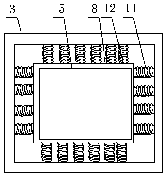
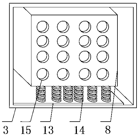
[0016] like Figure 1-3 As shown, a battery shock absorber for a new energy vehicle includes an outer shell 3 and an inner shell 8, the outer surface of the outer shell 3 is evenly opened with outer through holes 9, and the inner shell 8 is arranged inside the outer shell 3, And the middle positions of both sides of the outer shell 3 are provided with a card slot 2, a nut 1 is arranged in the card slot 2, and a nut 10 is arranged at a position close to the card slot 2 of the nut 1, the inner wall of the outer shell 3 and the inner shell Multiple groups of first springs 11 and second springs 12 are arranged between the outer walls of the body 8, and one end of the first springs 11 and the second springs 12 is welded on the inner wall of the outer c...


PUM


Abstract

The invention discloses a battery shock absorber of a new energy automobile. The battery shock absorber of the new energy automobile comprises an outer shell and an inner shell; the outer surfaces allaround the outer shell are evenly opened with outer through holes; clamping slots are opened at the middle positions of both sides of the outer shell; a nut is arranged in the clamping slot, and a screw cap is arranged at a position of the nut near the clamping slot; plurality sets of first springs and second springs are arranged between the inner wall of the outer shell and the outer wall of theinner shell; one end of the first spring and one end of the second spring are welded to the inner wall of the outer shell; and the other ends of the first spring and the second spring are welded to the outer wall of the inner shell. According to the battery shock absorber of the new energy automobile, through setting the corresponding through holes, the heat generated by the battery can be dissipated out, which can avoid overheating of the battery; through setting the springs between each of the walls, the shock absorbing effect can be improved; in addition, the battery shock absorber of thenew energy automobile is convenient to close the cover plate, which is convenient and brings better use prospects.

Description

technical field [0001] The invention relates to the field of auto parts, in particular to a battery shock absorber for a new energy vehicle. Background technique [0002] The car will vibrate during operation, and the battery installed on the car will also vibrate. The battery shock absorber can prevent the battery from vibrating and prolong the service life of the battery; the existing car shock absorber has certain disadvantages in use. The shock absorbing spring is only installed on the side wall, which reduces the shock absorbing effect, and the battery is in a relatively closed space, so the heat generated cannot be dissipated, which will reduce the service life of the battery. In addition, additional parts are required to cover the cover. Plates increase the cumbersomeness of use and have a certain impact on the use of automobile shock absorbers. Therefore, we propose a battery shock absorber for new energy vehicles. Contents of the invention [0003] The main purpo...

Claims


Application Information

Patent Timeline
IPC IPC(8): H01M2/04H01M2/10H01M10/613H01M10/625H01M10/6556H01M10/6562H01M50/15H01M50/166H01M50/202H01M50/231H01M50/242H01M50/249H01M50/262H01M50/271
CPCH01M10/6562H01M10/625H01M10/613H01M10/6556Y02E60/10H01M50/231H01M50/202H01M50/242H01M50/262H01M50/271
Inventor 柳海强
Owner NANJING LINGYA AUTOMOBILE TECH RES INST
Learn More