
Machining Error Compensation Method of Thin-walled Parts Based on Mirror Image Method and Cubic Spline Interpolation

A technology of thin-walled parts processing and spline interpolation, which is applied in the direction of program control, instrument, computer control, etc., can solve the problems of ignoring the influence of processing deformation, complicated compensation process, and low compensation efficiency, so as to reduce the number of compensations and improve the compensation process. Simple, precision-enhancing effect

Active Publication Date: 2021-06-25
TIANJIN UNIVERSITY OF TECHNOLOGY
View PDF6 Cites 0 Cited by
  • Summary
  • Abstract
  • Description
  • Claims
  • Application Information

AI Technical Summary

Problems solved by technology

[0005] The purpose of the present invention is to provide a thin-walled part based on the mirror image method and cubic spline interpolation in order to overcome the defects of complex compensation process, low compensation efficiency and neglect of the influence of compensation amount on machining deformation in the existing machining error compensation method. Processing Error Compensation Method

Method used


Image

  • Machining Error Compensation Method of Thin-walled Parts Based on Mirror Image Method and Cubic Spline Interpolation
  • Machining Error Compensation Method of Thin-walled Parts Based on Mirror Image Method and Cubic Spline Interpolation
  • Machining Error Compensation Method of Thin-walled Parts Based on Mirror Image Method and Cubic Spline Interpolation

Examples


Embodiment Construction

[0032] The present invention will be further described below in conjunction with the accompanying drawings and specific embodiments, but the following embodiments in no way limit the present invention.

[0033] Taking thin-walled aluminum alloy workpieces as an example, the process of error compensation processing for thin-walled parts using the mirror image method and cubic spline interpolation error compensation method is described in detail as follows:

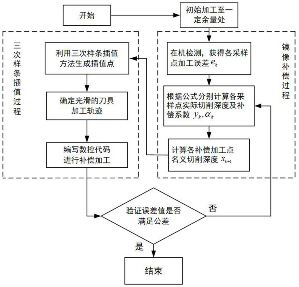
[0034] Such as figure 1 As shown, the steps of the thin-walled part processing error compensation method are as follows:

[0035] S1. Process the initial blank to leave a certain margin of 3mm;

[0036] S2. Using the on-machine detection system, the machining error e of the workpiece surface is detected according to a certain sequence of sampling points on the workpiece surface after step S1 is completed. k ={e k1 、e k2 ,...,e kn}, and calculate the actual cutting depth value y of the corresponding sampling point seque...


PUM


Abstract

The invention discloses a method for compensating processing errors of thin-walled parts based on mirror image method and cubic spline interpolation. The method sequentially processes initial blanks to a position with a certain margin and uses an on-machine detection system to obtain corresponding sampling points. Machining error e at k and the actual depth of cut value y k , Calculate the compensation coefficient α k Then get the nominal depth of cut x in the next compensation machining k+1 , Finally, use the cubic spline interpolation method to generate a limited number of interpolation points according to the size of the interpolation interval to obtain the optimal tool machining path; this method is based on the on-machine detection data, and establishes an optimized mirror image error compensation model by introducing compensation coefficients, combined with The cubic spline interpolation method generates enough interpolation points to obtain the optimal tool machining path, thereby simplifying the machining error compensation model of thin-walled parts, improving compensation efficiency and ensuring machining accuracy.

Description

technical field [0001] The invention relates to the technical field of precision cutting of machine tools, in particular to a method for compensating processing errors of thin-walled parts based on a mirror image method and cubic spline interpolation. Background technique [0002] With the rapid development of CNC machining technology, the processing precision of thin-walled parts in mold manufacturing, optical equipment, aerospace, medical and other fields is getting higher and higher. Whether it can produce high-precision products has become a standard for measuring the level of a country's manufacturing industry. . In the actual cutting process, the mechanical and thermal coupling effect generated by the relative motion between the tool and the workpiece causes the tool to produce continuous elastic-plastic deformation and severe vibration, resulting in a gap between the actual surface of the workpiece after machining and the design surface before machining. It has a dev...

Claims


Application Information

Patent Timeline
Patent Type & Authority Patents(China)
IPC IPC(8): G05B19/404
Inventor 刘振忠朱海星刘高领
Owner TIANJIN UNIVERSITY OF TECHNOLOGY
Learn More