Resistance measurement circuit, temperature detection circuit and charging gun
A temperature detection circuit and resistance measurement technology, applied in the electronic field, can solve problems such as inaccurate resistance measurement, achieve the effects of interference suppression, signal detection, and increase signal-to-noise ratio
- Summary
- Abstract
- Description
- Claims
- Application Information
AI Technical Summary
Problems solved by technology
Method used
Image
Examples
Embodiment 1
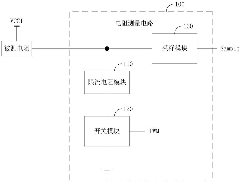
[0031] figure 1 The structure of the resistance measuring circuit provided by an embodiment of the present invention is shown. For the convenience of description, only the parts related to the embodiment of the present invention are shown, and the details are as follows:
[0032] like figure 1 As shown, the resistance measurement circuit 100 provided by the embodiment of the present invention is used to measure the resistance value of the measured resistance, and includes a current limiting resistance module 110 , a switch module 120 and a sampling module 130 .
[0033] The first end of the measured resistance is connected to the power supply voltage VCC1, the second end of the measured resistance is connected to the first end of the current limiting resistance module 110 and the input end of the sampling module 130, and the second end of the current limiting resistance module 110 is passed through The switch module 120 is grounded.
[0034] The switch module 120 is turned o...
Embodiment 2
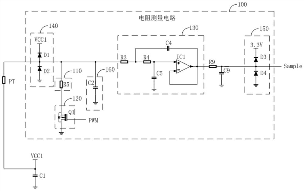
[0072] like figure 2 As shown, the embodiment of the present invention also provides a temperature detection circuit, including a thermistor PT and a resistance measurement circuit connected to the thermistor PT for measuring the resistance value of the thermistor PT as described in Embodiment 1 100, the thermistor PT is the measured resistance.
[0073] The model of the thermistor PT is PT1000.
[0074] In one embodiment, the on-off switching of the switch module 120 in the resistance measurement circuit 100 is controlled according to whether temperature measurement is required.
[0075] The on-off switching of the switch module 120 can also be determined by the preset time period of temperature collection, for example, when the temperature needs to be collected, the switch module 120 switches continuously, and when the temperature does not need to be collected, the switch module 120 remains off.
[0076] It can be understood that since the rated power of the PT1000 is at ...
Embodiment 3
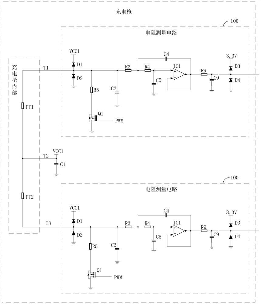
[0080] like image 3 As shown, the embodiment of the present invention also provides a charging gun, which is characterized in that it includes a preset number of temperature detection circuits as described in Embodiment 2, wherein a thermistor is installed inside the charging gun for measuring The internal temperature of the charging gun.
[0081] like image 3 As shown, in one embodiment of the present invention, the charging gun includes two temperature detection circuits, wherein two thermistors are respectively used to measure the temperature of the positive bus and the negative bus inside the charging gun.
[0082] In one embodiment, the thermistor PT1 is attached to the positive bus bar inside the charging gun, and the thermistor PT2 is attached to the negative bus bar inside the charging gun.
[0083] Among them, such as image 3 As shown, the connection mode of the thermistor in the charging gun is as follows: the first end of the thermistor PT1 is drawn out through ...
PUM
| Property | Measurement | Unit |
|---|---|---|
| electrical resistance | aaaaa | aaaaa |
Abstract
Description
Claims
Application Information
 - R&D
- Intellectual Property
- Life Sciences
- Materials
- Tech Scout
- Unparalleled Data Quality
- Higher Quality Content
- 60% Fewer Hallucinations
Browse by: Latest US Patents, China's latest patents, Technical Efficacy Thesaurus, Application Domain, Technology Topic, Popular Technical Reports.
© 2025 PatSnap. All rights reserved.Legal|Privacy policy|Modern Slavery Act Transparency Statement|Sitemap|About US| Contact US: help@patsnap.com


