
Integrated stove with oil pollution decomposition device and method

An integrated stove and oil pollution technology, applied in the field of integrated stoves, can solve problems such as time-consuming and labor-intensive exhaust pipe sucking, fan damage, etc., and achieve the effects of reducing noise, improving efficiency, and ensuring normal emissions

Pending Publication Date: 2019-05-17
浙江蓝炬星电器有限公司
View PDF5 Cites 4 Cited by
  • Summary
  • Abstract
  • Description
  • Claims
  • Application Information

AI Technical Summary

Problems solved by technology

[0003] The integrated stoves in the prior art generally can only absorb the oil fume, and the oil fume is separated through the oil fume separation net to reduce the oil content when the gas is discharged, but it will still entrain harmful gas and discharge it into the environment, so the oil fume discharged through the liquid The effect of purification treatment will be better. When the existing integrated stove is performing liquid purification treatment, it is easy to cause the suction of the exhaust pipe, so that the liquid is adsorbed to the smoke collection chamber through the exhaust pipe, which not only easily causes damage to the fan, but also cannot The treatment of the purification solution requires manual cleaning, which is time-consuming and labor-intensive

Method used


Image

  • Integrated stove with oil pollution decomposition device and method
  • Integrated stove with oil pollution decomposition device and method
  • Integrated stove with oil pollution decomposition device and method

Examples


Embodiment Construction

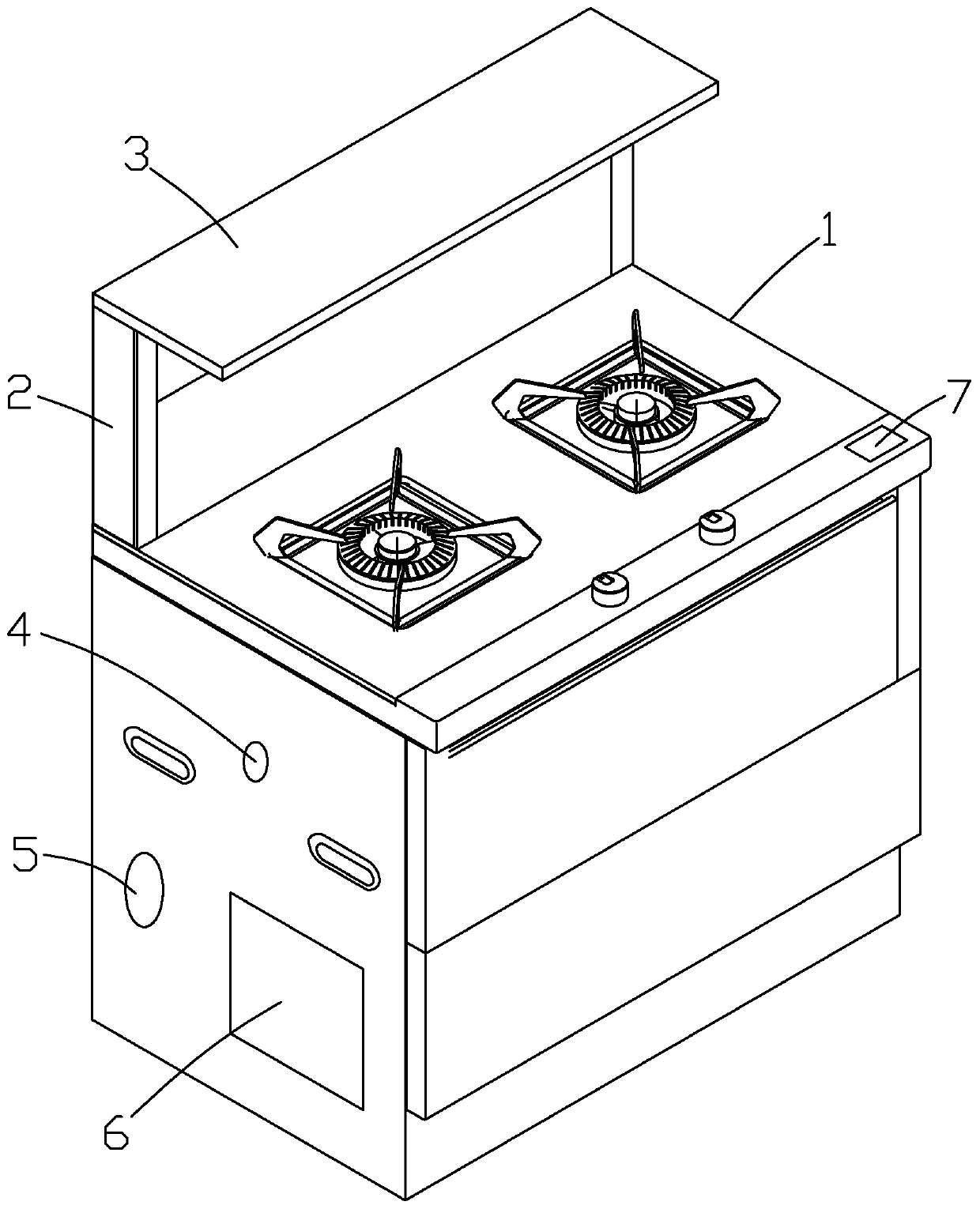
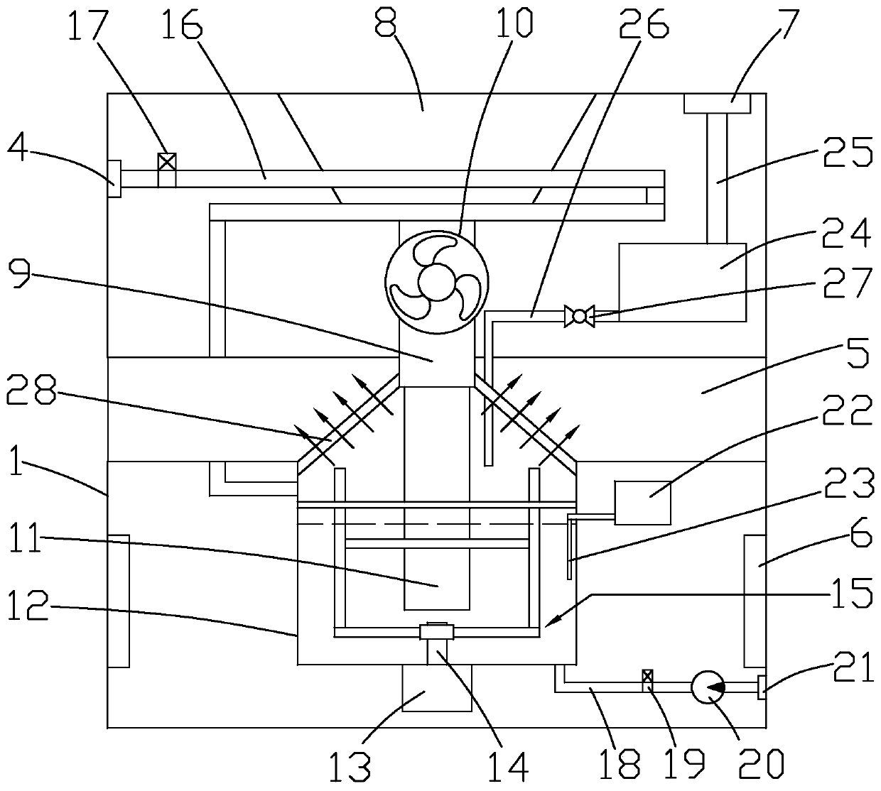
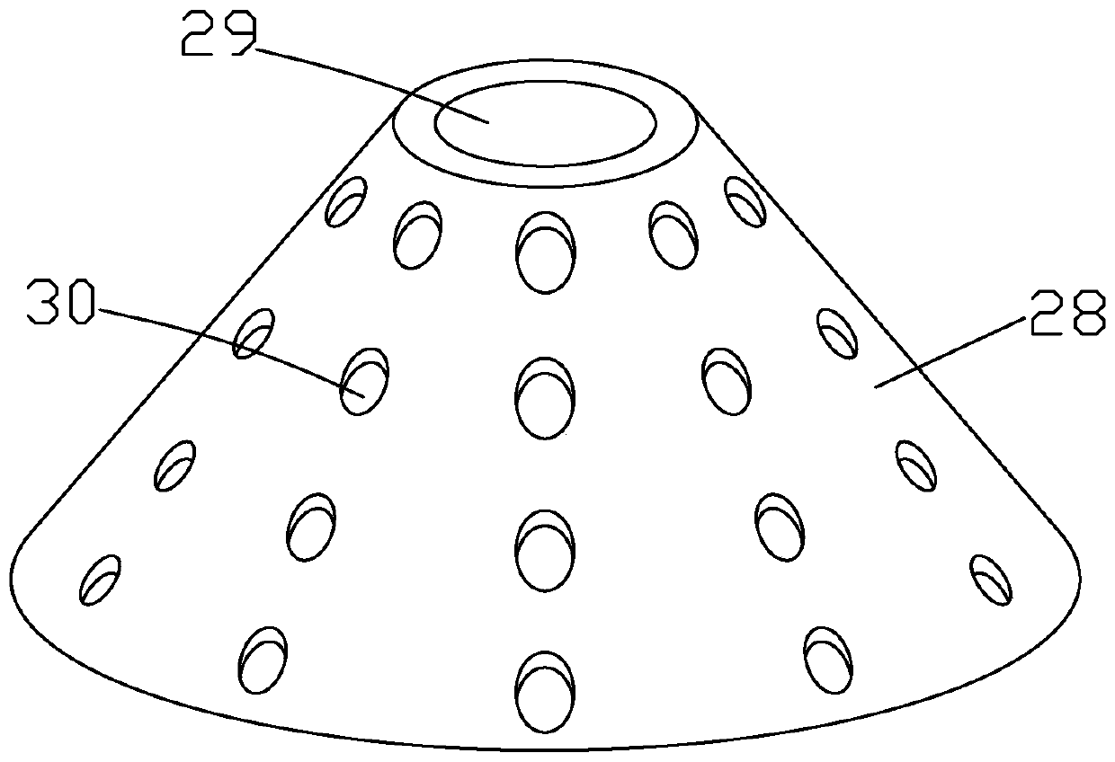
[0054] Such as Figure 1 to Figure 6 Shown here is an integrated stove with a device for decomposing oil pollution of the present invention, including an integrated stove body 1. A smoke guide plate 3 is horizontally arranged on the top surface of the integrated stove body 1, and the smoke guide plate 3 is connected to the integrated stove through a support column 2. The main body 1, the integrated stove body 1 is provided with a smoke collecting cavity 8, a smoke exhaust pipe 9 and an air outlet duct 5. The smoke collecting cavity 8 is fixedly connected to the top of the smoke exhaust pipe 9, and the smoke exhaust pipe 9 is provided with a fan 10, The air outlet air duct 5 is horizontally arranged in the integrated stove body 1, a box body 12 is arranged under the air outlet air duct 5, and the box body 12 is connected with the air outlet air duct 5, and protective doors 6 are symmetrically arranged on both sides of the integrated stove body 1 to protect The design of the door...


PUM


Abstract

The invention discloses an integrated stove with an oil pollution decomposition device and a method. The integrated stove with the oil pollution decomposition device comprises an integrated stove body, a smoke collecting cavity, a smoke exhaust pipe and an air outlet wind duct are arranged in the integrated stove body, a box body is arranged under the air outlet wind duct, and an anti-backflow pipe is arranged at the bottom of the smoke exhaust pipe. A mixing mechanism is arranged in the box body, a water delivery system is arranged on the side surface of the box body, a decomposition liquid storage mechanism is arranged above the air outlet wind duct, and a testing mechanism is arranged on the side surface of the box body. The method comprises the steps of the installation of the box bodyand the mixing mechanism, the installation of the anti-backflow pipe and an air outlet cover, the installation of the water delivery system, the installation of the decomposing liquid storage mechanism, the installation of the testing mechanism, the installation of a burner and a smoke guide plate and the trial operation of the integrated stove. According to the integrated stove with the oil pollution decomposition device and the method, through the design of the anti-backflow pipe, liquid in the box body can be prevented from being absorbed inversely while oil fume is discharged, the bottomend of the anti-backflow pipe is immersed in the liquid, the contact area between the adsorbed oil fume and the liquid can be increased, and the adsorption and decomposition efficiency of the oil fumein gas is improved.

Description

Technical field [0001] The invention relates to an integrated stove with an oil pollution decomposition device and a method. Background technique [0002] Integrated stove, also known as environmentally friendly stove or integrated environmentally friendly stove in the industry, is a kitchen appliance that integrates various functions such as range hood, gas stove, disinfection cabinet, storage cabinet, etc., which saves space and has a good effect of extracting smoke. Energy saving, low consumption and environmental protection. [0003] The integrated stoves in the prior art generally can only absorb oil fume. The oil fume is separated through the fume separation network, which reduces the oil content when the gas is discharged, but it still entrains harmful gases and is discharged into the environment. Therefore, the oil fume is discharged by the liquid. The purification treatment effect will be better. When the existing integrated stove is performing liquid purification treatme...

Claims


Application Information

Patent Timeline
Patent Type & Authority Applications(China)
IPC IPC(8): F24C15/20B01F7/16
Inventor 钱松良宋烨锋
Owner 浙江蓝炬星电器有限公司
Learn More