Movable temporary supporting device and rib expanding and mounting integrated construction method
A temporary support and mobile technology, which is applied in the direction of earth square drilling, mine roof support, mining equipment, etc., can solve the problems of easy toppling of the device and insufficient stability of the support column, and achieve the effect of ensuring reliable support
- Summary
- Abstract
- Description
- Claims
- Application Information
AI Technical Summary
Problems solved by technology
Method used
Image

Examples
Embodiment 1
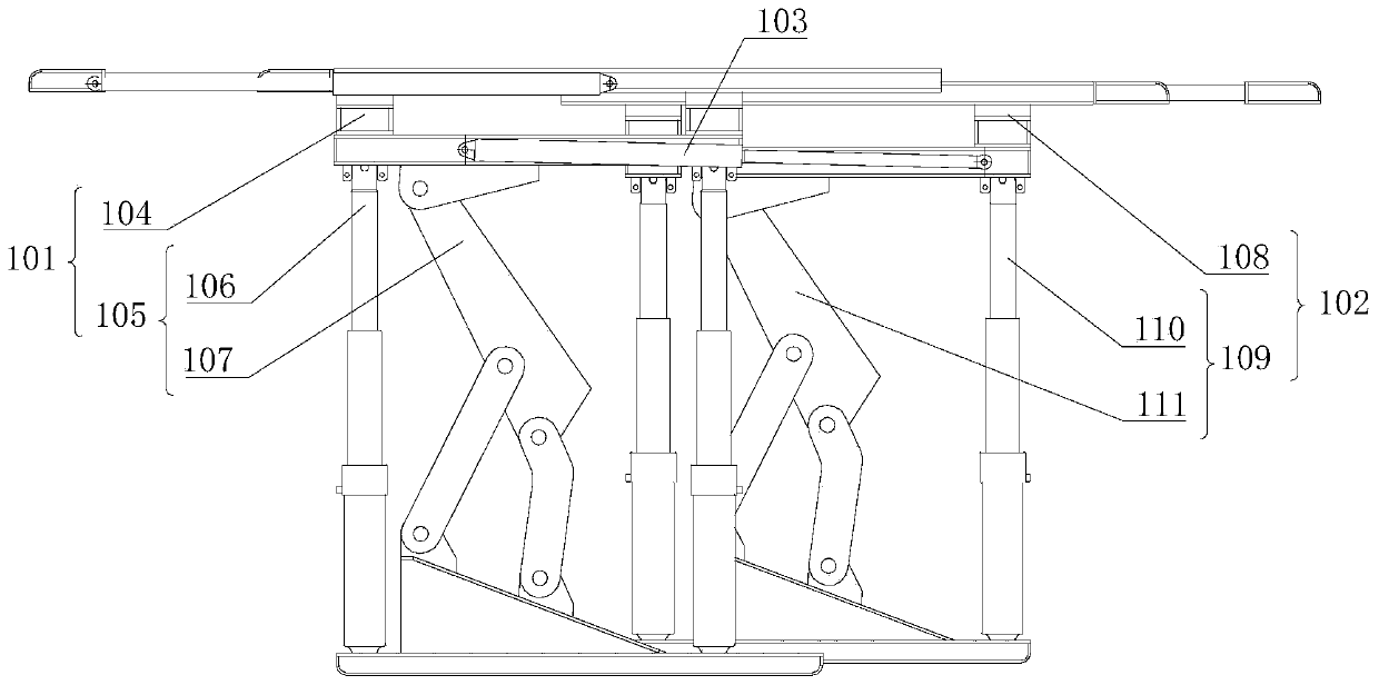
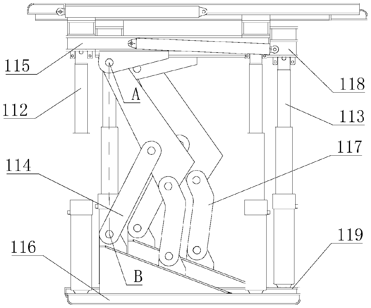
[0043] see figure 1 with figure 2 as shown, figure 1 The first structural schematic diagram of the mobile temporary support device provided in Embodiment 1 of the present application; figure 2 It is a schematic diagram of the second structure of the mobile temporary support device provided in Embodiment 1 of the present application.
[0044] The mobile temporary support device provided by the application includes a first supporting device 101, a second supporting device 102 and a frame-moving driving device 103; both the first supporting device 101 and the second supporting device 102 are used to support the roadway Top surface; the mounting end of the frame-moving drive device 103 is connected with the first top support device 101, and the output shaft of the frame-shift drive device 103 is connected with the second top support device 102; The first driving action to move away from the direction of the first supporting device 101, and the frame shifting driving device 10...
Embodiment 2
[0060]The mobile temporary support device in the second embodiment is an improvement on the basis of the above-mentioned embodiment. The technical content disclosed in the above-mentioned embodiment will not be described repeatedly, and the content disclosed in the above-mentioned embodiment also belongs to the content disclosed in the second embodiment. .
[0061] see Figure 4 with Figure 5 , Figure 4 A schematic diagram of the first structure of the mobile temporary support device provided in Embodiment 2 of the present application; Figure 5 It is a schematic diagram of the second structure of the mobile temporary support device provided in the second embodiment of the present application.
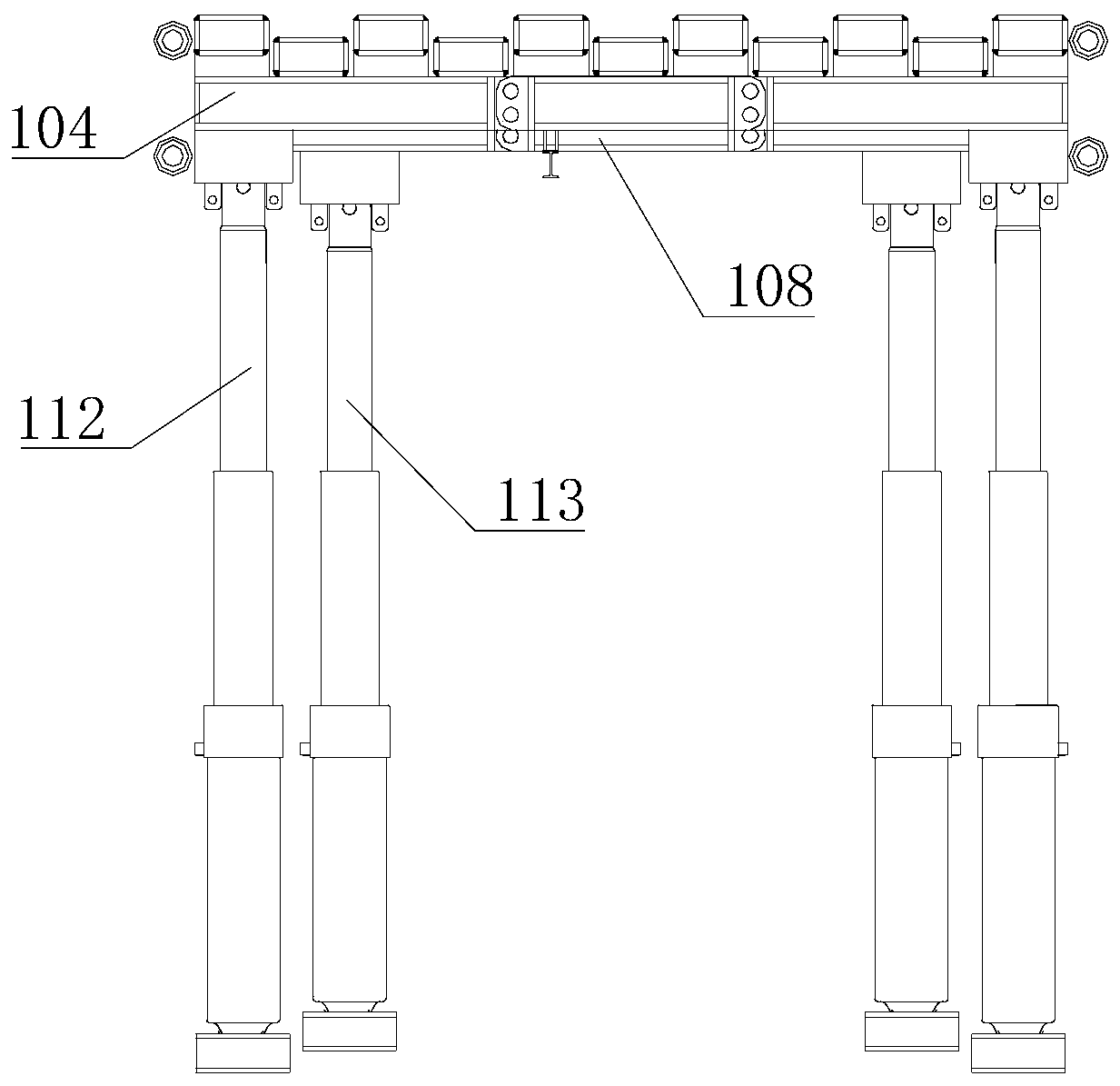
[0062] In an optional solution of this embodiment, the first roof support 104 includes a plurality of first roof longitudinal beams 120 arranged at intervals; the second roof support 108 includes a plurality of second roof longitudinal beams 121 arranged at intervals; A first roo...
Embodiment 3
[0070] Embodiment 3 of the present application provides an integrated construction method for side expansion and installation, including the following steps:
[0071] Step 100: After initializing the side expansion, install the hydraulic support to support the top surface of the roadway, install the mobile temporary support device in any one of the above-mentioned embodiments on one side of the hydraulic support to support the top surface of the roadway, and transfer the excavator to the mobile Within the accommodation range of the temporary support device;
[0072] Step 200, drive the reloading excavator to dig forward, and drive the mobile temporary support device to move forward synchronously;
[0073] Step 300 , after the mobile temporary support device moves a set distance, install hydraulic supports sequentially behind the mobile temporary support device.
[0074] The integrated construction method of side expansion and installation provided by this application uses the...
PUM
 Abstract
Description
Claims
Application Information
 - R&D
- Intellectual Property
- Life Sciences
- Materials
- Tech Scout
- Unparalleled Data Quality
- Higher Quality Content
- 60% Fewer Hallucinations
Browse by: Latest US Patents, China's latest patents, Technical Efficacy Thesaurus, Application Domain, Technology Topic, Popular Technical Reports.
© 2025 PatSnap. All rights reserved.Legal|Privacy policy|Modern Slavery Act Transparency Statement|Sitemap|About US| Contact US: help@patsnap.com