
Glass pedal connection device and mounting method thereof

An installation method and pedal technology, applied in the direction of pedals, building structures, stairs, etc., can solve the problems of extremely high installation requirements and complicated processes, and achieve the effect of reducing construction accuracy requirements and easy installation.

Active Publication Date: 2019-05-17
深圳市极尚建设集团股份有限公司
View PDF5 Cites 2 Cited by
  • Summary
  • Abstract
  • Description
  • Claims
  • Application Information

AI Technical Summary

Problems solved by technology

[0004] The above-mentioned existing technical solutions have the following defects: each set of splicing devices needs to be precisely adjusted to meet the installation requirements of tempered glass, so that each set of splicing devices can share the force, and there will be no The total load is within the design range, but the tempered glass is broken due to excessive local force
Therefore, the connection device requires extremely high installation requirements for construction personnel, and it needs to be constantly adjusted and tested during the construction process, and the process is extremely complicated.

Method used


Image

  • Glass pedal connection device and mounting method thereof
  • Glass pedal connection device and mounting method thereof
  • Glass pedal connection device and mounting method thereof

Examples


Embodiment 1

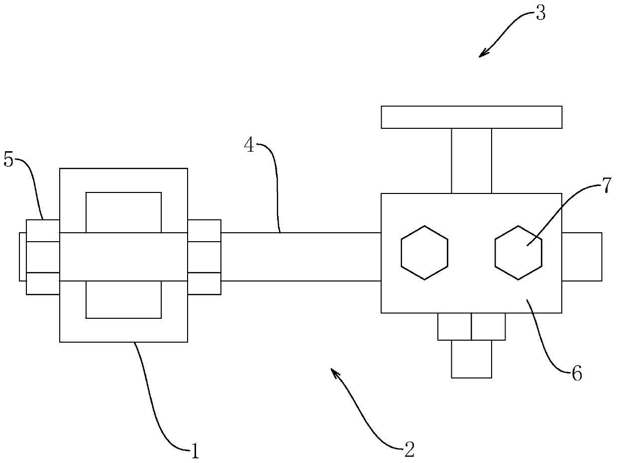
[0041] Such as figure 1 As shown, a glass pedal docking device includes a support frame 1, a movable frame 2 connected to the support frame 1, and a support member 3 connected to the upper end of the movable frame 2 and abutted against tempered glass.

[0042] Such as figure 1 As shown, the movable frame 2 includes two horizontal rods 4 parallel to and passing through the support frame 1, and the horizontal rods 4 are respectively threaded with first fixing nuts 5 at the two ends of the supporting frame 1, and are supported by the first fixing nuts 5. The two ends of frame 1 fix the position of horizontal bar 4. One end of the horizontal rod 4 away from the support frame 1 is slidably connected with a horizontal seat 6, and the side of the horizontal seat 6 is threadedly connected with a first adjusting bolt 7. The position is fixed.

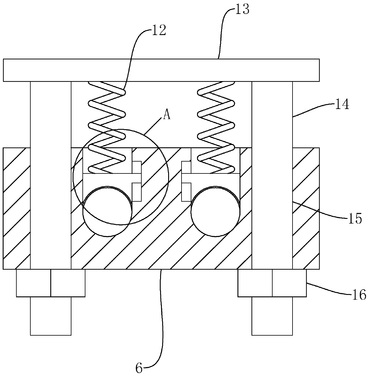
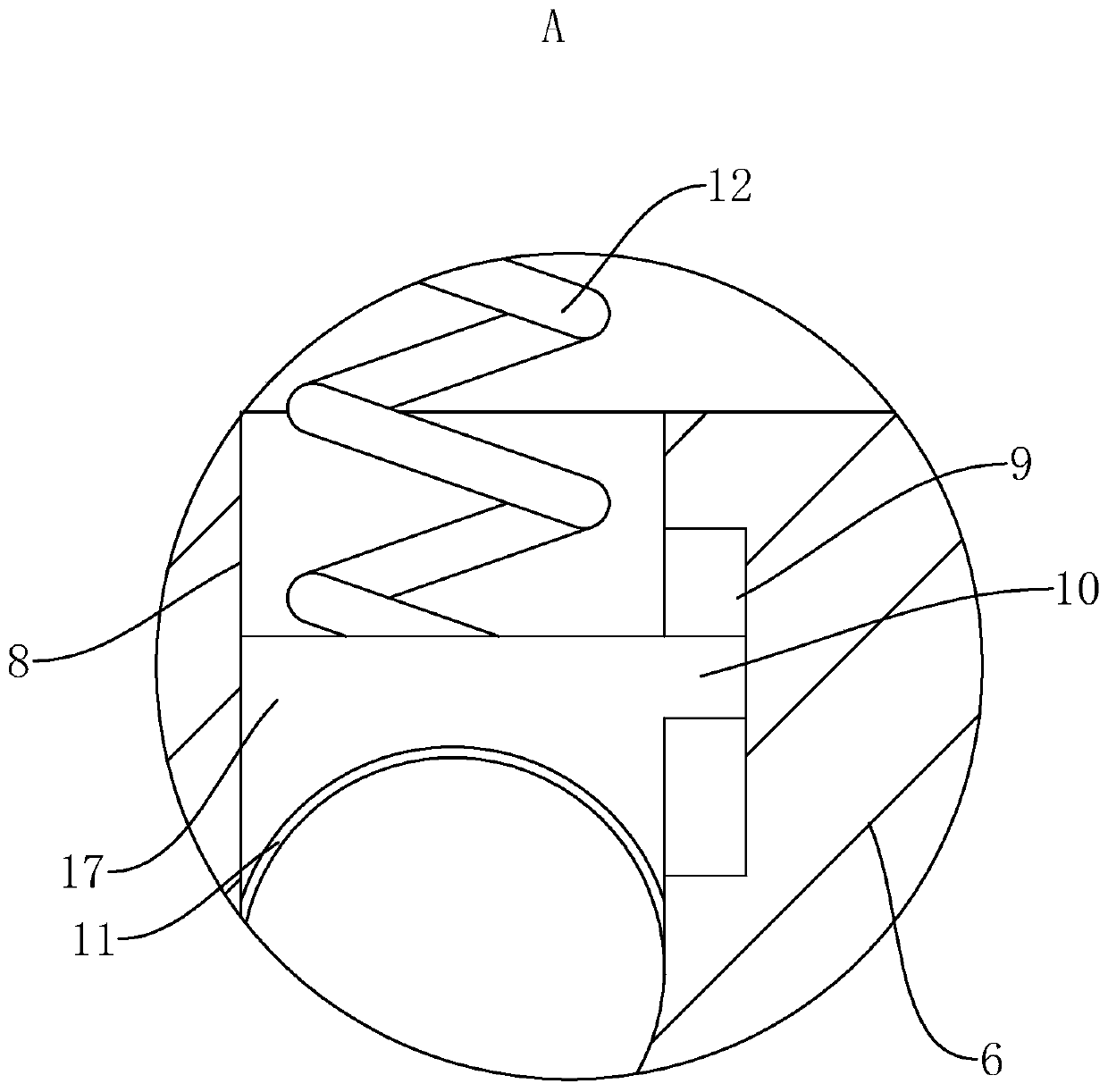
[0043] Such as figure 2 with image 3 As shown, the upper surface of the level seat 6 is respectively opened with a through hole 8 connec...

Embodiment 2

[0046] A method for installing a glass pedal, comprising:

[0047] Step 1, install the horizontal bar 4;

[0048] After screwing on a first fixing nut 5 on the horizontal bar 4, pass the threaded end of the horizontal bar 4 through the support frame 1 and then lock the horizontal bar 4 by the first fixing bolt, so that the horizontal bar 4 is fixed on the support frame 1 on.

[0049] Step 2, adjust the movable frame 2;

[0050] When adjusting the position of the level seat 6 to the set place, the position of the movable frame 2 is preliminarily fixed by tightening the first adjusting bolt 7 .

[0051] Step 3, initially extruding the stage clip 12;

[0052] Tighten the second adjusting nut 16 so that the compression spring 12 is squeezed and contracted. At this time, the compression amount of the compression spring 12 is less than the expected compression amount of the tempered glass installed. At this moment, under the pressure of the compression spring 12, the movable block...


PUM


Abstract

The invention relates to the technical field of glass pedals, in particular to a glass pedal connection device and a mounting method thereof. The glass pedal connection device comprises a supporting frame, a movable frame connected with the supporting frame, and a supporting piece connected to the upper end of the movable frame and abutted with toughened glass; the movable frame comprises two parallel horizontal rods and a horizontal seat slidably connected to the horizontal rods; vertical guide holes are formed in the horizontal seat; the supporting piece comprises a pressure spring with oneend matched with the horizontal seat, and a supporting disk fixedly connected to the upper end of the pressure spring; at least two guide columns vertically passing through the guide holes are weldedto the supporting disk; the parts, passing through the horizontal seat, of the lower ends of the guide columns are in threaded connection with second adjustment nuts. After the glass pedal is mountedon the supporting disk, the glass pedal is leveled by rotating the second adjustment nuts. Since the pressure spring enables the supporting disk to be abutted with the glass pedal, several errors alsocan be compensated under the action of the pressing spring by timely adjustment.

Description

technical field [0001] The invention relates to the technical field of glass pedals, in particular to a glass pedal docking device and an installation method thereof. Background technique [0002] With the wide application of glass, more and more stairs, platforms, etc. use glass as a supporting structure, that is, as a glass tread. The use of glass pedals can not only meet the functional needs, but also play a decorative role. [0003] The utility model patent whose existing authorized notification number is CN207048209U discloses a kind of glass pedal connecting device for building. In this solution, the position in the horizontal direction is adjusted through the cooperation of the locking nut and the first connecting piece, and the height position of the docking device in the vertical direction is adjusted through the cooperation of the second connecting piece, the fixing nut and the locking bolt. [0004] The above-mentioned existing technical solutions have the follo...

Claims


Application Information

Patent Timeline
IPC IPC(8): E04F11/022E04F11/104E04F11/116
Inventor 董子新林瑶袁岳阳
Owner 深圳市极尚建设集团股份有限公司
Learn More