
A hinged automatic drive unit and a folding support arm driven by a folding screw

An automatic drive and lead screw drive technology, applied in the aerospace field, can solve the problems of difficult antennas, small folding ratio, and limited deployment range, and achieve the effects of wide application range, improving folding ratio, and saving launch costs

Active Publication Date: 2022-07-01
HARBIN INST OF TECH
View PDF9 Cites 0 Cited by
  • Summary
  • Abstract
  • Description
  • Claims
  • Application Information

AI Technical Summary

Problems solved by technology

[0003] In order to solve the problem that the existing folding support arm depends on the drive of the hinge spring and the lead screw, the folding ratio is small, the expansion range is limited, and it is difficult to provide stretching and supporting functions as a relatively large antenna, etc., and provides a Articulated automatic drive unit and folding support arm driven by folding screw

Method used


Image

  • A hinged automatic drive unit and a folding support arm driven by a folding screw
  • A hinged automatic drive unit and a folding support arm driven by a folding screw
  • A hinged automatic drive unit and a folding support arm driven by a folding screw

Examples


specific Embodiment approach 1

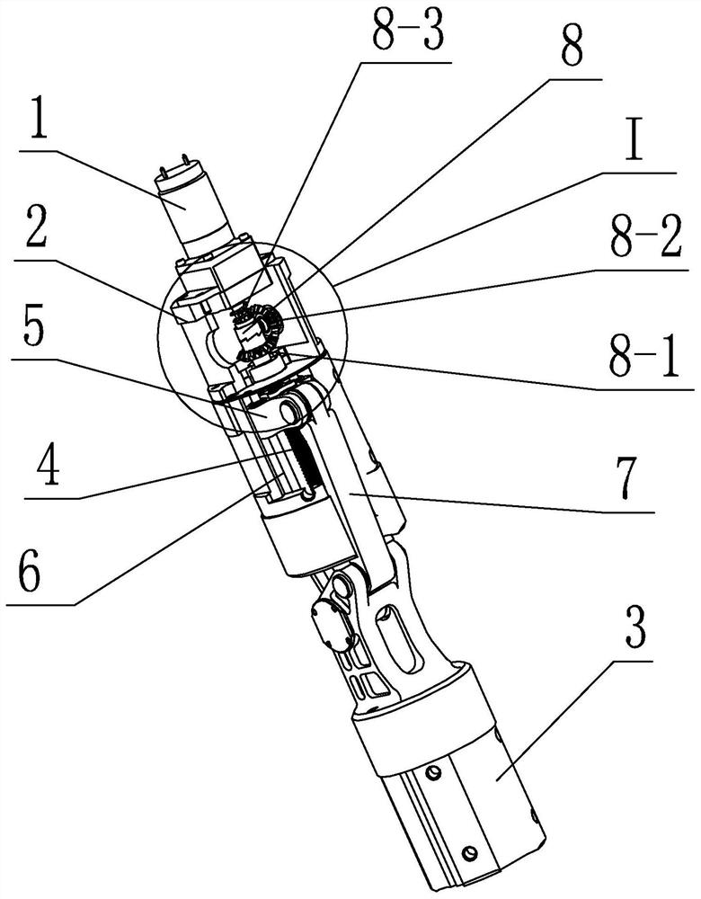
[0031] Embodiment 1: Combining figure 1 and figure 2 To illustrate this embodiment, an articulated automatic drive unit of this embodiment includes a motor 1 , a first connecting body 2 , a second connecting body 3 , a lead screw 4 , a nut 5 , a guide rod 6 and a connecting rod 7 ;

[0032] The first connecting body 2 and the second connecting body 3 are hinged. The first connecting body 2 is provided with a lead screw 4 and a guide rod 6. The axis of the lead screw 4 and the axis of the guide rod 6 are parallel to each other, and the lead screw 4 is driven by the motor 1 , the screw 4 is provided with a screw nut 5, the screw nut 5 is slidably arranged on the guide rod 6, one end of the connecting rod 7 is hinged with the screw nut 5, the other end of the connecting rod 7 is hinged with the second connecting body 3, and the connecting rod 7 The axis hinged with the second connecting body 3 and the axis where the first connecting body 2 is hinged with the second connecting b...

specific Embodiment approach 2

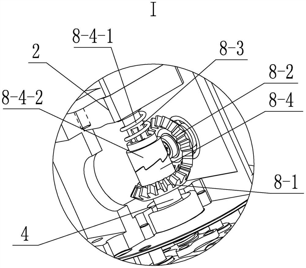
[0034] Specific implementation mode 2: Combining figure 1 and figure 2 To illustrate this embodiment, a manual drive device 8 is further provided between the lead screw 4 and the shaft of the motor 1 in this embodiment. The manual drive device 8 includes a first bevel gear 8-1, a second bevel gear 8-2, and a transmission shaft. 8-3 and one-way rotating mechanism 8-4;

[0035] The transmission shaft 8-3 is fixed on the shaft of the motor 1, a one-way rotation mechanism 8-4 is arranged between the end of the transmission shaft 8-3 and the end of the lead screw 4, and the lead screw 4 is fixed with a first bevel gear 8-1. The second bevel gear 8-2 is arranged on the first connecting body 2 through the rotating shaft, and the first bevel gear 8-1 and the second bevel gear 8-2 mesh with each other.

[0036] Other components and connection relationships are the same as in the first embodiment.

specific Embodiment approach 3

[0037] Specific implementation three: combination figure 2 To illustrate this embodiment, the one-way rotation mechanism 8-4 of this embodiment includes a first compression spring 8-4-1 and two ratchet toothed sleeves 8-4-2;

[0038] One of the ratchet toothed sleeves 8-4-2 is slidably arranged on the transmission shaft 8-3 and can rotate together with the transmission shaft 8-3. The first compression spring 8-4-1 is sleeved on the transmission shaft 8-3 and the two The ends respectively press on the first connecting body 2 and the end of one of the ratchet toothed sleeves 8-4-2, and the other ratchet toothed sleeve 8-4-2 is fixed on the end of the lead screw 4, The ratchet teeth on the two ratchet toothed sleeves 8-4-2 cooperate with each other under the action of the first compression spring 8-4-1.

[0039] The transmission shaft 8-3 can be a spline shaft, or a square shaft or other shaft that can generate torque to one of the ratchet toothed sleeves 8-4-2, and can make th...


PUM


Abstract

A hinged automatic drive unit and a folding support arm driven by a folding screw, belonging to the field of aerospace technology, to solve the problem that the existing folding support arm relies on the driving of hinge springs and screws to unfold, the folding ratio is small, and it is difficult to be used as a Larger antennas, etc. provide extension and support functions. The invention includes a motor, a first connecting body, a second connecting body, a lead screw, a screw nut, a guide rod and a connecting rod; the first connecting body and the second connecting body are hinged, and the first connecting body is provided with a lead screw and a guide rod The axis of the rod, the axis of the lead screw and the axis of the guide rod are parallel to each other. The lead screw is driven by a motor. The lead screw is provided with a nut, which is slidably arranged on the guide rod. One end of the connecting rod is hinged with the nut, and the other side of the connecting rod is hinged. One end is hinged with the second connecting body, and the hinged axis of the connecting rod and the second connecting body and the hinged axis of the first connecting body and the second connecting body are parallel to each other. The invention is suitable for the support of aerospace antennas.

Description

technical field [0001] The invention specifically relates to a hinged automatic drive unit and a folding and unfolding support arm driven by a folding screw, belonging to the field of aerospace technology. Background technique [0002] With the development of aerospace technology and the further exploration and utilization of my country's aerospace industry, large-scale deployment antennas, deep space probes, rigid and flexible solar wings, space stations, etc., have become the main objects of exploration and design by researchers in the field of aerospace in my country . Throughout the domestic development needs, the requirements for the expansion ratio, precision and stiffness of the spacecraft system are getting higher and higher, so it is necessary to design a high-performance folding support arm. As a basic one-dimensional deployment mechanism and support mechanism, the folding support arm can be used as a large-scale deployment antenna, solar wing, space manipulator an...

Claims


Application Information

Patent Timeline
Patent Type & Authority Patents(China)
IPC IPC(8): B64G1/22B64G1/44
Inventor 郭宏伟马小飞邓宗全刘荣强杨德文
Owner HARBIN INST OF TECH
Learn More