
Glue supply device used for continuous, stable and uniform glue coating and glue liquid coating method

A glue supply device and glue coating technology, which is applied to the surface coating liquid device, coating, etc., can solve the problems of discontinuous and stable pressure and the inability to achieve a stable and uniform coating effect, so as to achieve stable and uniform thickness and avoid Effect of corrugated coating

Active Publication Date: 2019-05-17
宁波甬安光科新材料科技有限公司
View PDF11 Cites 5 Cited by
  • Summary
  • Abstract
  • Description
  • Claims
  • Application Information

AI Technical Summary

Problems solved by technology

Because the pressure generated by the pump is usually discontinuous and stable, it is impossible to achieve a stable and uniform coating effect

Method used

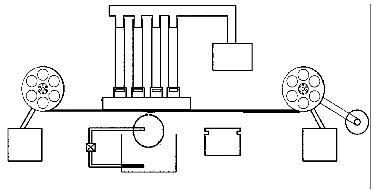

Image

  • Glue supply device used for continuous, stable and uniform glue coating and glue liquid coating method
  • Glue supply device used for continuous, stable and uniform glue coating and glue liquid coating method
  • Glue supply device used for continuous, stable and uniform glue coating and glue liquid coating method

Examples


Embodiment 1 1 Embodiment approach

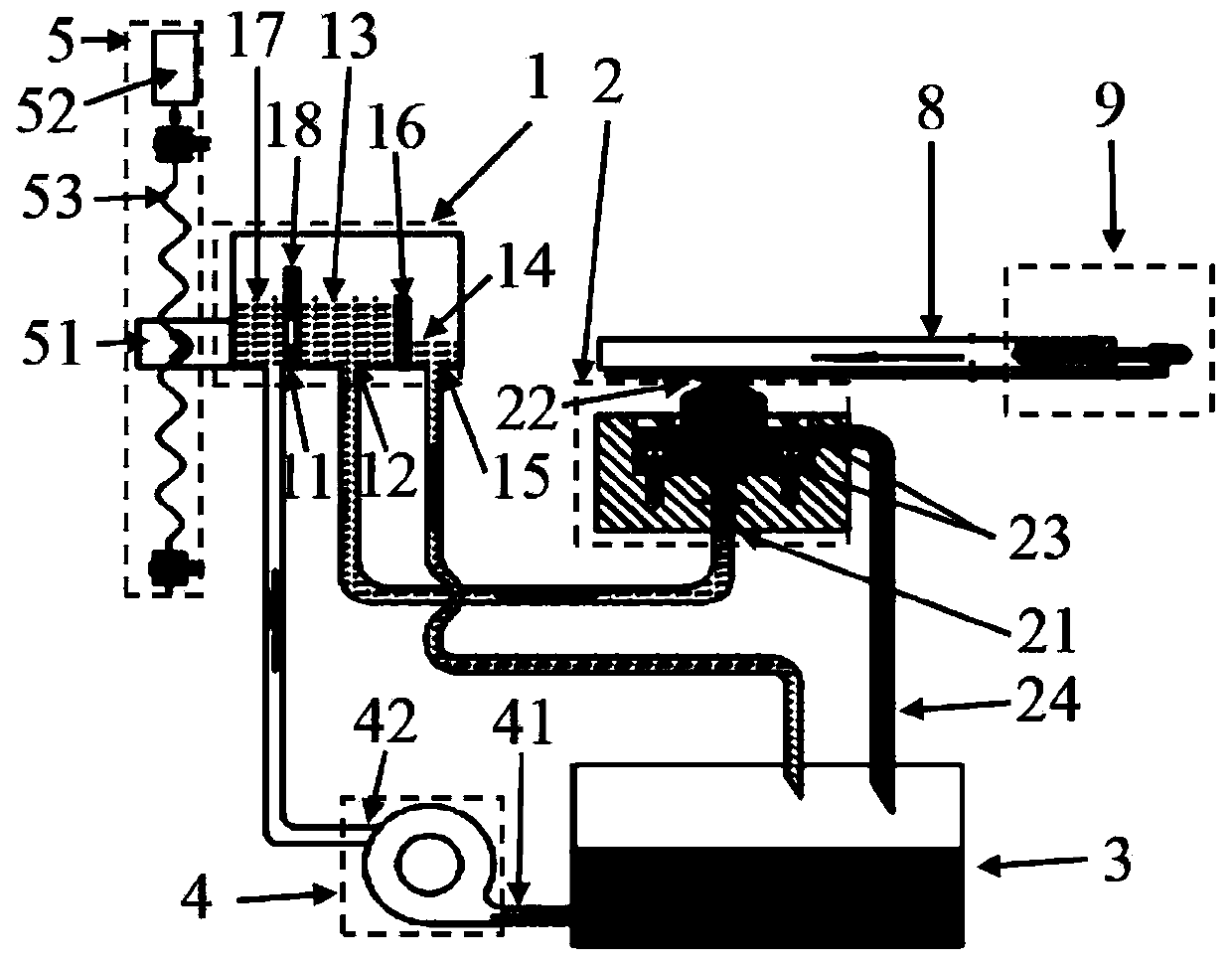
[0039] An embodiment of the glue supply device is as figure 2 As shown, the glue supply device includes a glue supply container (1), a glue spraying device (2), a low glue storage container (3), a liquid delivery device (4), a lifting device (5), a low glue storage container storage table ( 6), anti-vibration device (7). The glue supply container (1) includes the glue inlet (11), the glue outlet (12), the glue supply area (13), the overflow glue area (14), the overflow glue opening (15), the partition a (16), the buffer area (17), partition b (18), the glue inlet (11) is located in the buffer zone (17), the glue outlet (12) is located in the glue supply area (13), and the glue overflow port (15) is located in the glue overflow area ( 14), the glue supply area (13) and the overflow glue area (14) are separated by the partition a (16), the buffer zone (17) and the glue supply area (13) are separated by the partition b (18), the partition b ( 18) is higher than the partition a...

Embodiment 2

[0041] Embodiment 2 An embodiment of the meniscus gluing equipment of the present invention

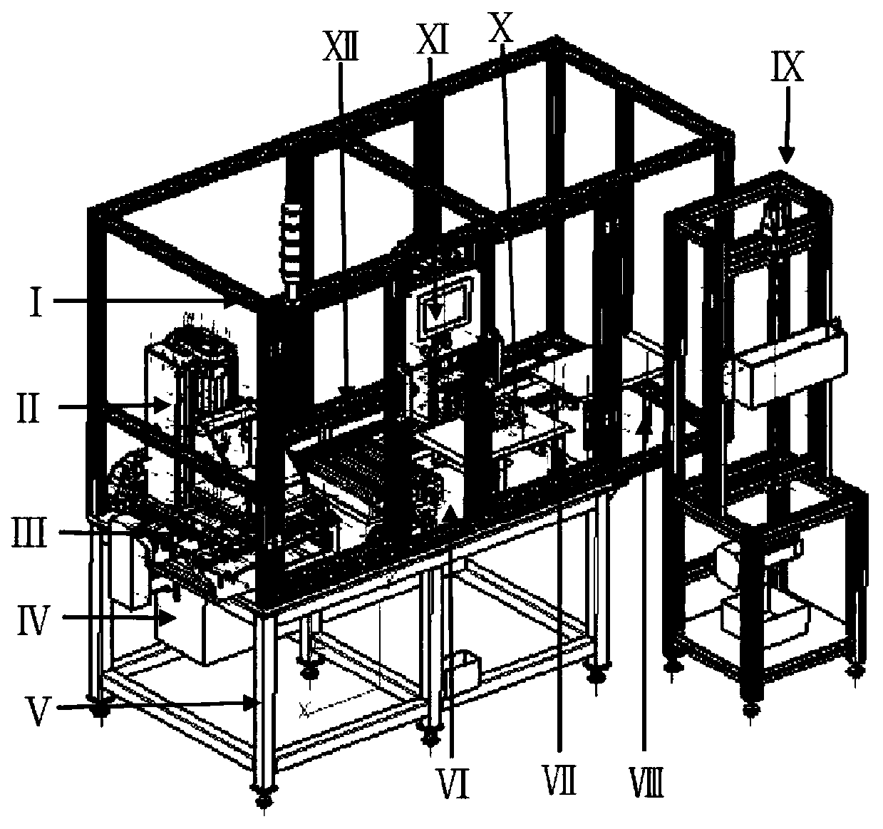
[0042] An embodiment of the meniscus gluing equipment for continuous, stable and uniform gluing is as follows: image 3 shown.

[0043] This gluing equipment includes equipment dust cover (Ⅰ), coating film element suction mechanical arm (II), coating film element positioning and loading table (Ⅲ), PLC control cabinet (IV), equipment support (Ⅴ), equipment support table (Ⅵ), product turning transition frame (Ⅶ), product turning unloading table (Ⅷ), glue supply device (Ⅸ), product turning manipulator (Ⅹ), central control panel (Ⅺ), linear motor drive guide rail (Ⅻ). Among them, the glue supply device is as described in Example 1, including a glue supply container (1), a glue spraying device (2), a low-level glue storage container (3), a liquid delivery device (4), a lifting device (5), a low-level glue storage Glue container storage table (6), anti-vibration device (7). Coating compo...

Embodiment 3

[0045] Embodiment 3 The influence of the position of the glue supply container on the state of glue application among the present invention

[0046] Such as Figure 4 As shown, suppose that in the connecting device formed by the glue supply container (1) and the glue spraying device (2), the vertical distance between the glue spraying port and the lowest point of the connecting device is h 22 , when the glue supply container is in different positions A, B, and C, the vertical distances between it and the lowest point of the connector are h A 、h B 、h C . When the glue supply container is higher than the glue spraying device in the vertical direction, that is h A > h 22 , the pressure difference generated by the height difference of the liquid level on the lowest point of the connector will promote the glue liquid to flow to the glue spraying device. When the positions of the glue supply container and the glue spraying device are unchanged, the pressure difference remains c...


PUM


Abstract

The invention provides a glue supply device used for continuous, stable and uniform glue coating, and a glue liquid coating method, and belongs to the field of continuous production advection film coating. The glue supply device comprises a glue supply container, a glue spraying device, a low-position glue storage container and a liquid conveying device. The glue supply container comprises a glueinlet, a glue outlet and a glue supply area. The glue spraying device comprises a glue supply opening and a glue coating opening. The liquid conveying device comprises a liquid inlet and a liquid outlet. The liquid outlet of the liquid conveying device is connected with the liquid inlet of the glue supply container, the glue outlet of the glue supply container is connected with the glue supply opening of the glue spraying device, the low-position glue storage container is connected with the liquid inlet of the liquid conveying device, and all connection mentioned above is pipeline connection.The height of the liquid level the glue supply area in the glue supply container is stable and controllable, the highest point of the liquid level is higher than the highest point of the liquid levelof the glue spraying opening in the glue spraying device in the vertical direction, the low-position glue storage container is connected with the liquid inlet of the liquid conveying device, and all connection mentioned above is pipeline connection. The height of the liquid level of the glue supply area in the glue supply container is stable and controllable, the highest point of the liquid levelis higher than the highest point of the liquid level of the glue spraying opening in the glue spraying device in the vertical direction, stable pressure is provided for glue liquid flowing of the gluespraying opening in the glue spraying device, and therefore continuous, stable and uniform glue coating can be achieved for meniscus film coating devices.

Description

technical field [0001] The invention belongs to the field of making stable and uniform single-sided continuous advection coating films, and in particular relates to an adjustable automatic, stable and uniform glue supply device and a glue coating method, which are applied to meniscus glue coating equipment. Background technique [0002] At present, many large-diameter optical switching devices, optical lenses, and optical displays need to be coated with a single film, some require a single-sided multi-layer film, and some require a double-sided heterogeneous film. Moreover, industrial coating requires continuous efficiency. At present, continuous coating of single-sided optical thin films is a common physical method in industry, such as magnetron sputtering is a commonly used method. The wet chemical method currently has a lifting method, but it cannot coat a single film, and the continuous film coating is also limited by equipment to a certain extent; although the spin coa...

Claims


Application Information

Patent Timeline
Patent Type & Authority Applications(China)
IPC IPC(8): B05C5/02B05C11/10
CPCY02P70/10
Inventor 胡文杰
Owner 宁波甬安光科新材料科技有限公司
Learn More