Coil winding equipment with self-expansion type winding shaft

A reel and self-expanding technology, which is applied in the manufacture of coils, electrical components, inductors/transformers/magnets, etc., can solve the problems of high labor costs, small size of high-frequency transformers, and inability to effectively adapt to high-frequency transformer coil shafts, etc., to achieve The effect of improving processing efficiency and reducing product defective rate

Active Publication Date: 2019-05-14
江苏华祥电子有限公司
View PDF5 Cites 2 Cited by
  • Summary
  • Abstract
  • Description
  • Claims
  • Application Information

AI Technical Summary

Problems solved by technology

[0002] High-frequency transformers are small in size, and the coil winding process usually uses manual winding or fixed shaft diameter to fix the end of the winding shaft for mechanical winding. Manual winding has high technical requirements for workers, and it is necessary to ensure that the tightness of each winding is the same. The cost is high, and the existing mechanical winding method cannot effectively adapt to high-frequency transformer coil shafts with different shaft diameters. The method of end fixing requires high pressure control accuracy, otherwise it is easy to cause extrusion deformation to the coil shaft, so a design is made. The mechanical winding equipment that can effectively overcome the defects of the existing technology is of great significance to the actual production and processing

Method used


Image

  • Coil winding equipment with self-expansion type winding shaft
  • Coil winding equipment with self-expansion type winding shaft
  • Coil winding equipment with self-expansion type winding shaft

Examples


Embodiment Construction

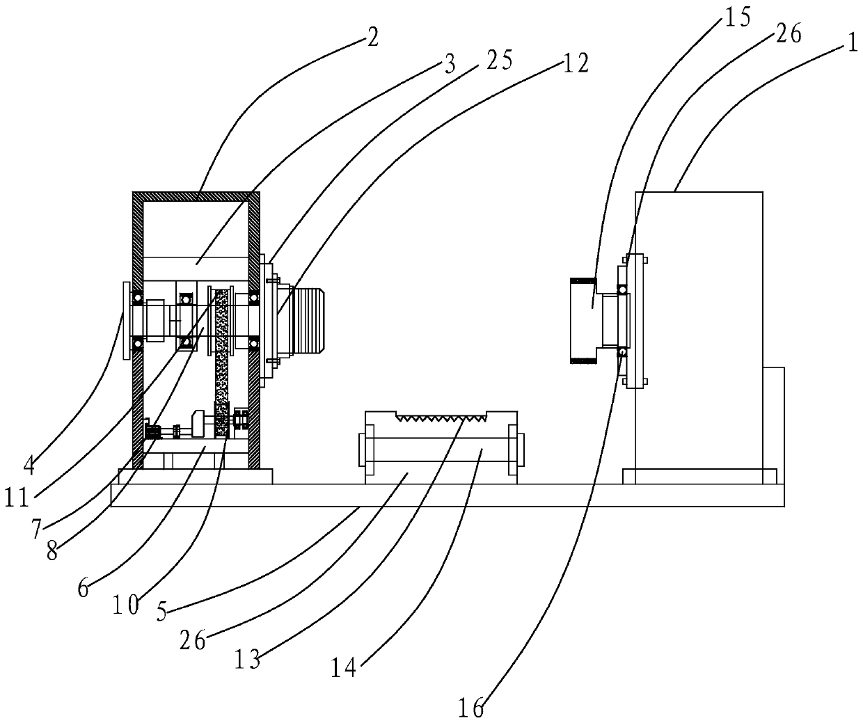
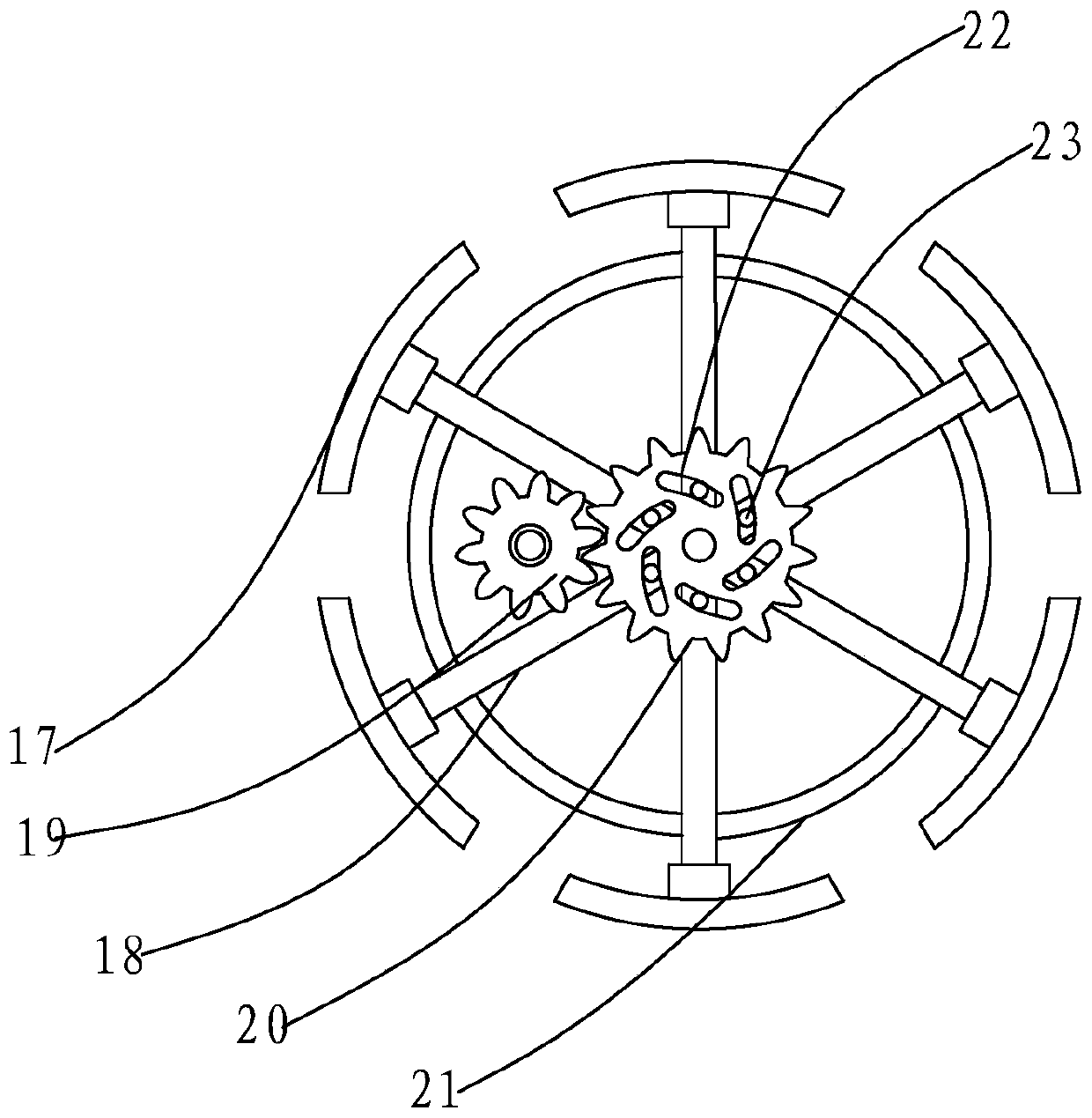
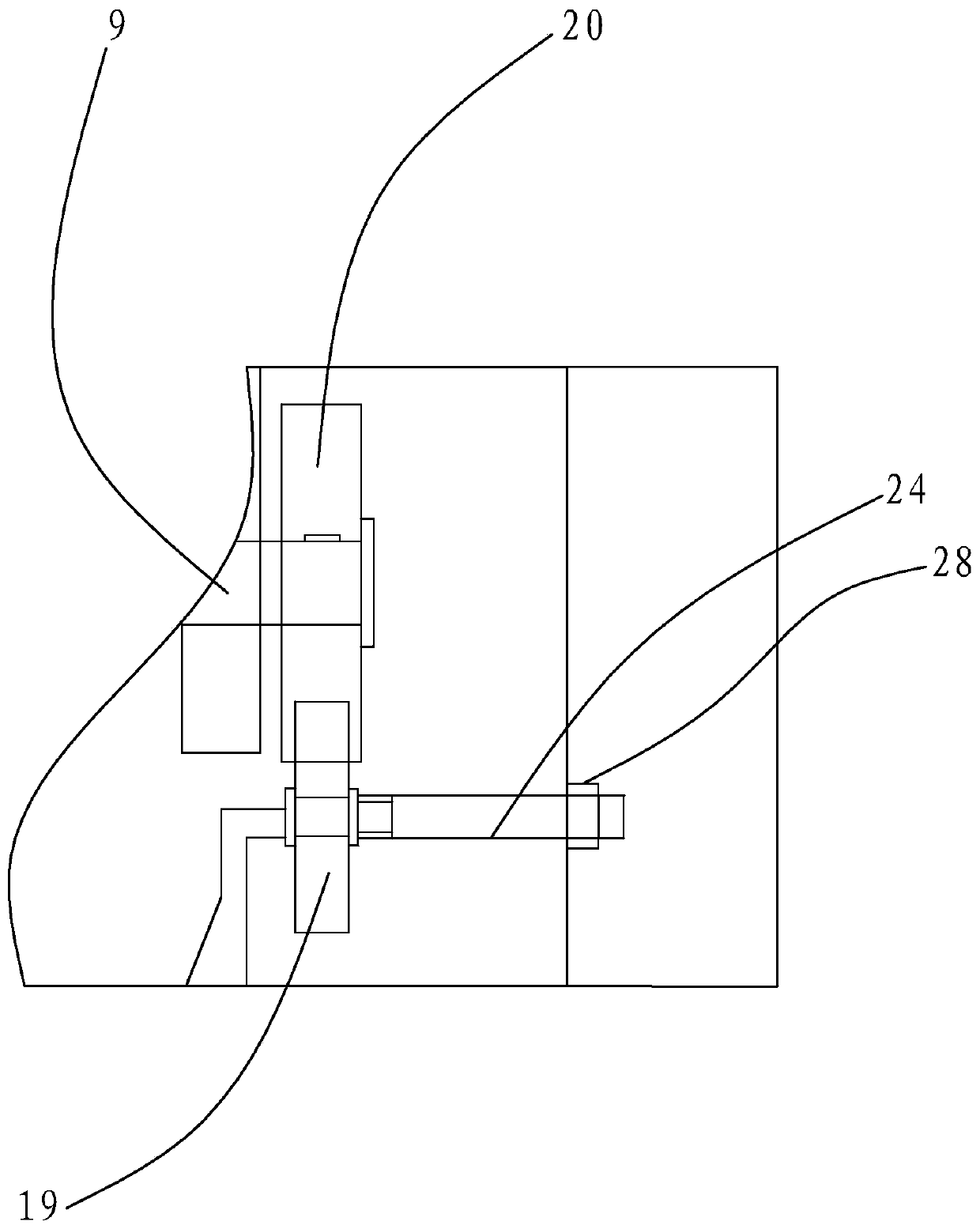
[0021] Such as figure 1 , 2 As shown in and 3, the present invention includes a working table 5, a power clamping table arranged on the working table 5, a fixed clamping table symmetrically arranged with the power clamping table 1, a reel device for fixing the coil shaft, and a power clamping table. The rotating seat 25 on the end surface of the clamping table, the driven seat 26 provided on the end surface of the fixed clamping table 1, and the toothed box 14 for cutting the insulating tape on the outer edge of the transformer. The toothed box 14 is provided in the middle of the worktable 5 and is empty The cavity is square, and a revolving shaft 14 is set up inside. The revolving shaft 14 is detachable and fixed. The revolving shaft 14 is interference-connected with a roll of insulating tape. The outlet 13 of the toothed box 27 has sharp teeth on one side and the other is smooth. Linear. The power clamping table includes a power clamping table outer shell 2, a fixed base fram...


PUM


Abstract

The invention discloses a coil winding equipment with a self-expansion type winding shaft. The equipment comprises a workbench, a power clamping table arranged on the workbench, a fixed clamping tablewhich is symmetric with the power clamping table, a winding shaft device used for fixing a coil shaft, a rotation seat arranged on the end surface of the power clamping table, a driven seat arrangedon the end surface of the fixed clamping table, and a tooth-shaped box used for clipping an insulated rubber tape on the outer edge of a transformer. The equipment abandons a traditional mechanical equipment principle, adopts a self-expansion design, can effectively adapt to the coiling machining operation of the coil shafts of different sizes and model numbers, avoids a situation that a traditional fixing way extrudes and damages the coil shaft, and also greatly improves machining efficiency.

Description

Technical field [0001] The invention relates to the field of high-frequency transformer processing, in particular to a reel self-expanding type coil winding device. Background technique [0002] The high-frequency transformer is small in size, and the coil winding process mostly uses manual winding or fixed shaft diameter winding shaft end for mechanical winding. Manual winding requires workers to operate with high technical requirements. It is necessary to ensure that the tightness of each winding is the same. The cost is high. The existing mechanical winding method cannot effectively adapt to the high frequency transformer coil shafts of different shaft diameters. The fixed end method requires high pressure control accuracy, otherwise it will easily cause extrusion deformation on the coil shaft, so a design is designed Mechanical winding equipment that can effectively overcome the defects of the prior art is of great significance to actual production and processing. Summary of...

Claims


Application Information

Patent Timeline
Patent Type & Authority Applications(China)
IPC IPC(8): H01F41/06H01F41/098H01F41/12
Inventor 金震华陈春香
Owner 江苏华祥电子有限公司
Why Eureka
Try Eureka