
Exhaust valve type carbon dioxide cracking pipe

A technology of carbon dioxide and exhaust pipes, which is applied in the direction of weapon accessories, blasting tubes, offensive equipment, etc., can solve the problems of reduced blasting power, insufficient inflation of cracked tubes, and low blasting power, so as to improve blasting power, high production efficiency, and blasting power huge effect

Inactive Publication Date: 2019-05-14
戴矿明
View PDF1 Cites 2 Cited by
  • Summary
  • Abstract
  • Description
  • Claims
  • Application Information

AI Technical Summary

Problems solved by technology

[0002] In the existing blasting technology, most of the blasting tubes are used to replace the traditional explosives during the blasting operation. The existing carbon dioxide blasting device, such as the carbon dioxide blasting device in the invention patent with application number 201520141713.X, has a top end of the blasting tube. A filling head with a filling hole. The filling head is provided with a valve core matching the filling hole and a terminal post matching the detonating device. The terminal post covered with an insulating tube is connected to the terminal screw. The tail of the blasting tube There is a venting head with a blasting hole and a decompression hole at the end, a bursting disc is set between the venting head and the blasting tube, the first wire passing through the venting head, the blasting tube, and the filling head and the first wire connected to the shell of the blasting tube The two wires are respectively connected to the power supply and can be used repeatedly, but the directional blasting force is small, and it is difficult to meet the blasting requirements for large-scale external operations. If there is too much moisture, the cracking tube will not be fully inflated during the inflation process, resulting in a decrease in blasting power

Method used


Image

  • Exhaust valve type carbon dioxide cracking pipe
  • Exhaust valve type carbon dioxide cracking pipe
  • Exhaust valve type carbon dioxide cracking pipe

Examples


Embodiment 1

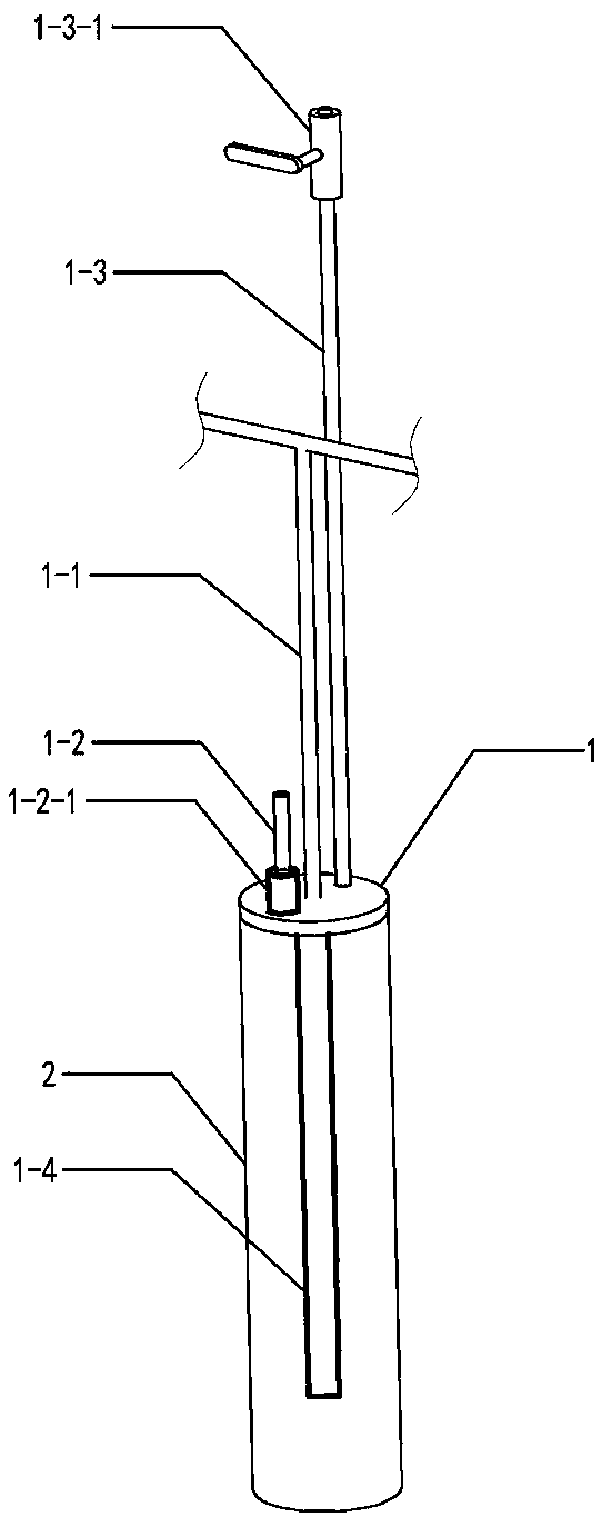
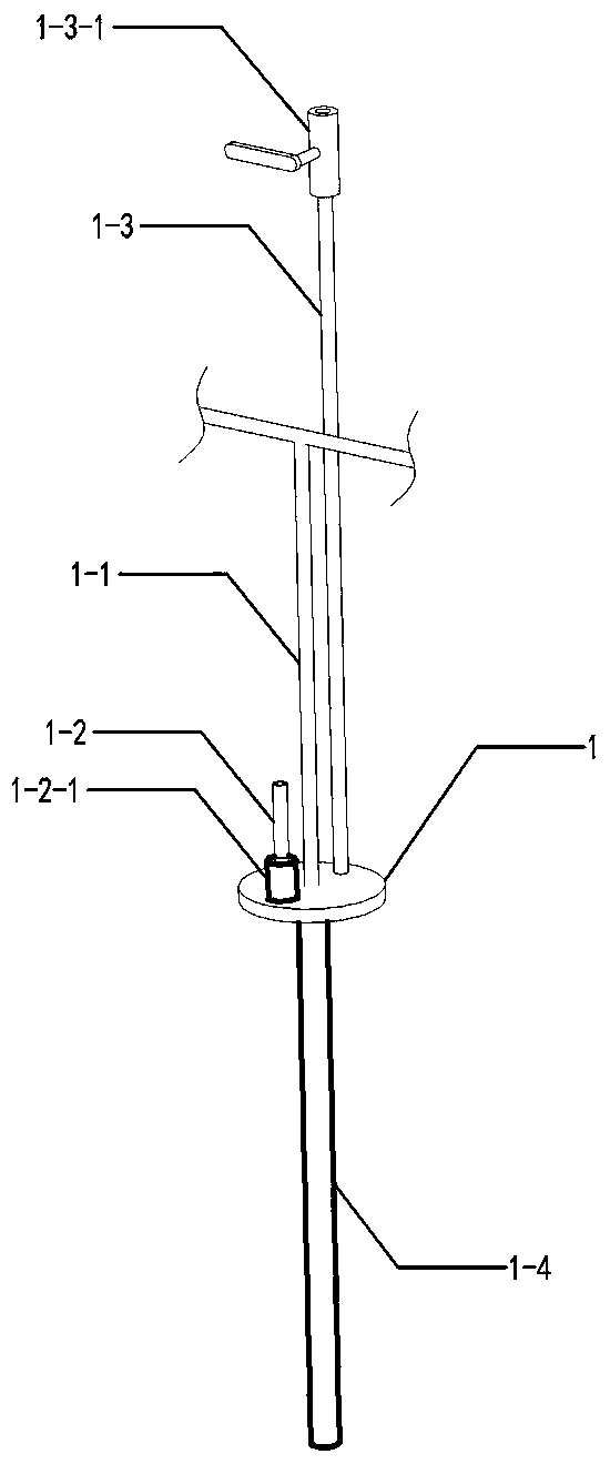
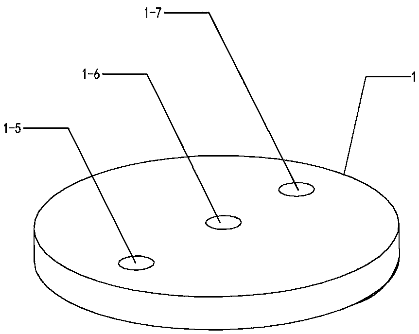
[0014] It can be seen from the content of the invention that an exhaust valve type carbon dioxide cracking tube is composed of a sealing plate 1, a tube body 2, an electronic fuze 1-1, an air intake pipe 1-2, an air intake check valve 1-2-1, an exhaust valve The air pipe 1-3, the exhaust pipe valve 1-3-1, and the heating pipe 1-4 are composed, and the sealing plate 1 is provided with an air inlet 1-5, a fuze hole 1-6, and an exhaust hole 1-7 ; The electronic fuze 1-1 passes through the fuze hole 1-6 and is connected to the explosive device 1-4; the air intake check valve 1-2-1 is installed in the air intake hole 1-5 and the air intake pipe 1-2 between; the lower end of the exhaust pipe 1-3 is welded to the mouth of the exhaust hole 1-7, and the exhaust pipe valve 1-3-1 is installed on the upper end of the exhaust pipe 1-3;

[0015] Sealing plate 1 described in the present invention refers to: the sealing plate of pipe body 2, its sealing effect; Draw the electronic fuze line ...

Embodiment 2

[0027] In order to realize the exhaust function of the present invention, an air intake pipe 1-2 and an exhaust pipe 1-3 are arranged on the sealing plate 1; the same end.

[0028] In order to realize the exhaust function of the cracking tube in the present invention, an exhaust pipe 1-3 is provided on the sealing plate 1 .

[0029] In order to realize rapid removal of impurities in the gas, the present invention designs the inlet pipe 1-2 and the exhaust pipe 1-3 at the same end of the exhaust-type cracking pipe.

[0030] The exhaust valve-type carbon dioxide cracking tube provided by the present invention is filled with liquid carbon dioxide inside and outside the tube of the exhaust-type cracking tube during use, and at the same time, a certain amount of gas is released by opening the valve 1-3-1 of the exhaust tube , after releasing for a certain period of time, close the exhaust pipe valve 1-3-1 to make it sealed, so that the gas in the exhaust-type cracking pipe is fill...


PUM


Abstract

The invention discloses an exhaust valve type carbon dioxide cracking pipe. The exhaust valve type carbon dioxide cracking pipe is composed of a sealing plate, a pipe body, an electronic fuze, an airinlet pipe, an air inlet one-way valve, an exhaust pipe, an exhaust pipe valve and a heating pipe. According to the exhaust valve type carbon dioxide cracking pipe, an exhaust pipeline is arranged, full filling can be well conducted on the liquid carbon dioxide capacity, the blasting power of a single exhaust type cracking pipe can be well improved, when a power supply is switched on through the electronic fuze, the heating pipe effects quickly, thus carbon dioxide in an outer pipe is instantly vaporized and expanded, the pressure in the pipe is increased rapidly, the outer pipe is expanded and bursted, the whole detonation process is fast, the production efficiency is high, the exhaust valve type carbon dioxide cracking pipe is smashed at one time, and the blasting power is high.

Description

Technical field: [0001] The invention relates to the technical field of blasting devices, in particular to an exhaust valve type carbon dioxide cracking tube. Background technique: [0002] In the existing blasting technology, most of the blasting tubes are used to replace the traditional explosives during the blasting operation. The existing carbon dioxide blasting device, such as the carbon dioxide blasting device in the invention patent with application number 201520141713.X, has a top end of the blasting tube. A filling head with a filling hole. The filling head is provided with a valve core matching the filling hole and a terminal post matching the detonating device. The terminal post covered with an insulating tube is connected to the terminal screw. The tail of the blasting tube There is a venting head with a blasting hole and a decompression hole at the end, a bursting disc is set between the venting head and the blasting tube, the first wire passing through the vent...

Claims


Application Information

Patent Timeline
IPC IPC(8): F42B3/04
Inventor 戴矿明
Owner 戴矿明
Learn More