
A dieless spinning method of equal-wall thickness of thin-walled truncated cone-shaped parts based on spherical spinner

A technology of dieless spinning and truncated cone, which is applied in the field of wall thickness dieless spinning, can solve problems such as thinning and difficult control of thinning rate, and achieve the effect of promoting application and improving product forming uniformity

Active Publication Date: 2020-03-24
SHENYANG AEROSPACE UNIVERSITY
View PDF5 Cites 0 Cited by
  • Summary
  • Abstract
  • Description
  • Claims
  • Application Information

AI Technical Summary

Problems solved by technology

With the development of science and technology, the research on spinning forming technology and theory has gone deep into spinning forming without core mold, and when spinning without core mold, the workpiece is suspended in the air, and it is affected by the spinning pressure during forming, which will lead to the deformation of the workpiece. Wall thickness is usually thinned, and the thinning rate is extremely difficult to control

Method used


Image

  • A dieless spinning method of equal-wall thickness of thin-walled truncated cone-shaped parts based on spherical spinner
  • A dieless spinning method of equal-wall thickness of thin-walled truncated cone-shaped parts based on spherical spinner
  • A dieless spinning method of equal-wall thickness of thin-walled truncated cone-shaped parts based on spherical spinner

Examples


Embodiment Construction

[0020] The present invention will be further described in detail below in conjunction with the accompanying drawings and specific embodiments.

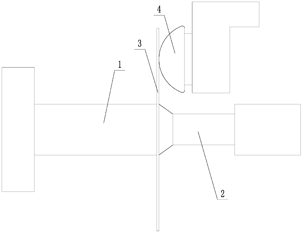
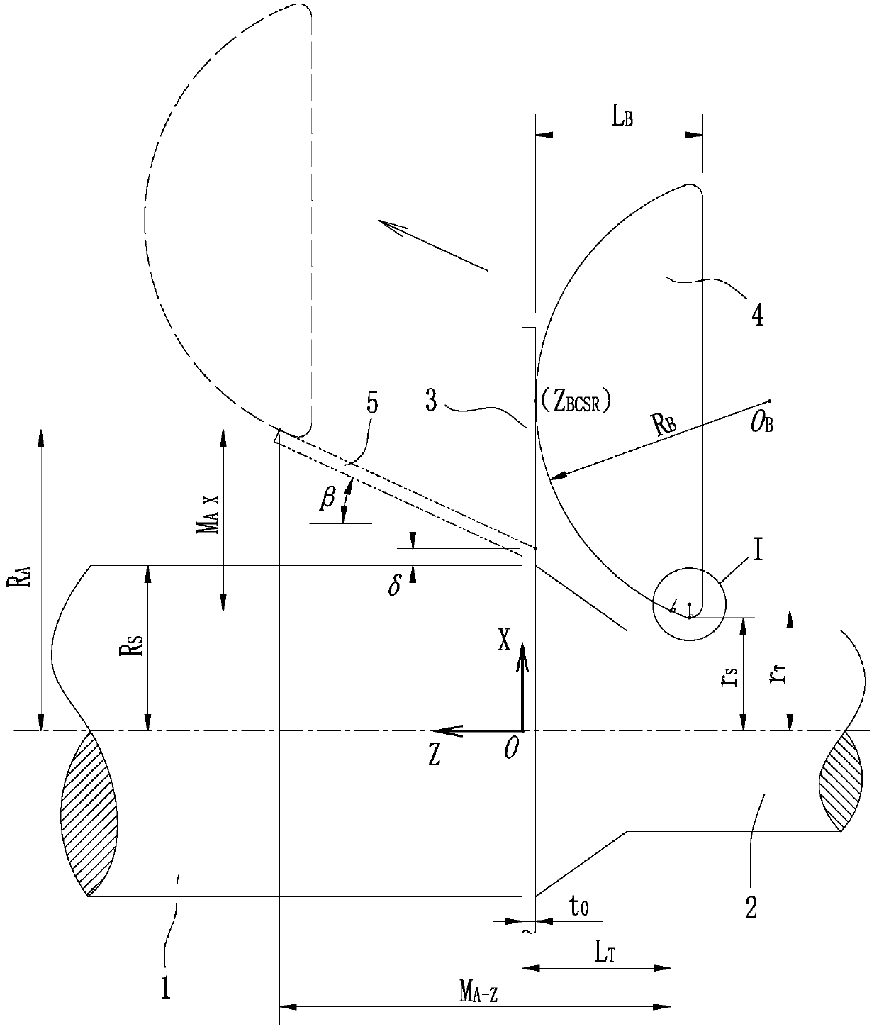
[0021] In this embodiment, the model of the CNC spinning machine is PS-CNCSXY-5, the CNC spinning machine has a built-in Siemens CNC system, and the rotating speed of the main shaft 1 is set to 200r / min; The plate thickness of the slab 3 is 2.05 mm, the material of the circular slab 3 is 6061-O aluminum alloy, the initial cross-sectional circle radius of the formed part 5 is 25 mm, and the axial depth of the formed part 5 is 16 mm. The half cone angle of the longitudinal section of 5 is 25°.

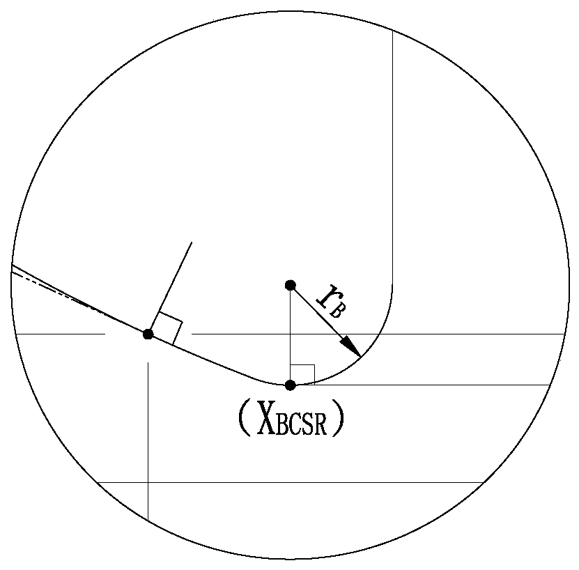
[0022] A method for dieless spinning of a truncated conical thin-walled part with equal wall thickness based on a spherical roller, comprising the following steps:

[0023] Step 1: Select a CNC spinning machine, press the circular slab 3 figure 1 The shown clamping is between the main shaft 1 and the tail top 2 of the CNC spinning machine to e...


PUM


Abstract

The invention provides an equal-wall-thickness mold-free spinning method based on a spherical spinning wheel and used for a circular-truncated-cone-shaped thin-walled workpiece. The equal-wall-thickness mold-free spinning method comprises the steps that a circular slab is clamped between a spindle and a tail ejector of a numerical-control spinning machine, the axis of the circular slab, the axis of the spindle and the axis of the tail ejector coincide, the axis of the spherical spinning wheel, the axis of the circular slab, the axis of the spindle and the axis of the tail ejector are located on the same horizontal plane, and the axis of the spherical spinning wheel is parallel to the spindle; the spherical spinning wheel is controlled to move along the Z axis till the spherical arc top makes contact with the to-be-spun surface of the circular slab, so that initial positioning of the spherical spinning wheel in the Z direction is completed; the spherical spinning wheel is controlled tomove along the X axis to complete initial positioning of the spherical spinning wheel in the X direction; the coordinates of a final contact point on the spherical spinning wheel in the initial spinning formation stage are determined; and the displacement in the X direction and the displacement in the Z direction of the final contact point on the spherical spinning wheel when all transformation ofa formed part is completed are determined; and determined relevant parameters are input to a system of the numerical-control spinning machine; and the numerical-control spinning machine is started, the mold-free spinning formation process is executed according to a machining procedure generated by the system till the circular slab is machined into the circular-truncated-cone-shaped formed part.

Description

technical field [0001] The invention belongs to the technical field of sheet metal spinning, and in particular relates to a dieless spinning method for a truncated conical thin-walled part with equal wall thickness based on a spherical rotary wheel. Background technique [0002] Spinning is widely used in aviation, aerospace, automobile and other industrial fields because of its high efficiency, low cost and high material utilization. Since the advent of modern spinning technology, scholars at home and abroad have carried out a lot of research work on the spinning forming of conventional rotary parts. After continuous improvement, the theory of precise and stable forming of circular cross-section spinning technology has been greatly developed. With the development of science and technology, the research on spinning forming technology and theory has gone deep into spinning forming without core mold, and when spinning without core mold, the workpiece is suspended in the air, a...

Claims


Application Information

Patent Timeline
Patent Type & Authority Patents(China)
IPC IPC(8): B21D22/14
Inventor 贾震谷立萍韩志仁姬书得刘宝明
Owner SHENYANG AEROSPACE UNIVERSITY
Learn More