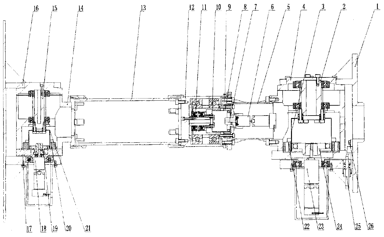
Three-degree-of-freedom high-precision drive device
A driving device, high-precision technology, applied in the direction of motor vehicles, transportation and packaging, aerospace equipment, etc., can solve the complex working mode of the attitude and orbit control system, the small range of rotation and pitch rotation angles, and the difficulty of signal and image information processing and other issues, to achieve the effect of facilitating the installation of the payload, reliable movement, and reducing the overall envelope size
Active Publication Date: 2015-01-14
SHANGHAI AEROSPACE SYST ENG INST
View PDF0 Cites 4 Cited by
- Summary
- Abstract
- Description
- Claims
- Application Information
AI Technical Summary
Problems solved by technology
a. It cannot meet the requirements of multi-degree-of-freedom driving of the payload, and usually requires the connection and combination of multiple single-degree-of-freedom driving devices to achieve the purpose of multi-degree-of-freedom driving. In this way, the size and weight of the mechanism increase accordingly, which brings launch costs increased;
b. It is not suitable for aircraft with high requirements for orbit change capability, such as aircraft orbit changes within a large range of 200-900km, of course, it also complicates the working mode of the attitude and orbit control system;
c. It is not suitable for the requirement that the payload needs to be adjusted arbitrarily, and its pointing accuracy is lower than 0.05°
In foreign countries, similar drive devices in the United States have been successfully applied to the drive of payloads on Mars rovers, but the range of rotation and pitch rotation angles of similar drive devices is small, and the deployment device adopts conic curve indirect deployment method, and its transmission chain is complicated; and The rotation angle range of its mechanism can only reach ±360°, and its rotation range has no overlapping area, which brings difficulties to signal, image and other information processing
Method used
View moreImage
Smart ImageViewing Examples
Examples
Embodiment Construction
Login to View More PUM
 Abstract
The invention discloses a three-degree-of-freedom high-precision driving device, which is applicable to various payloads (antennas, cameras, receivers, etc.) on a space vehicle to perform movements such as deployment, driving, scanning, and precise pointing. The three-degree-of-freedom high-precision driving device includes: an A-axis mechanism for driving pitching motion, a B-axis mechanism for driving steering motion, and a C-axis mechanism for driving unfolding motion. The A-axis machine can make the payload realize pitching and directional movement within the range of ±95°; the B-axis mechanism can make the payload realize the steering and directional movement within the range of ±185°; the C-axis mechanism can make the payload move within the range of 0°~90° It realizes deployment movement and directional tracking with directional antenna. The present invention adopts the integrated design technology, cleverly integrates the planetary gear reducer and the encoder inside the motor assembly, and designs a harmonic reducer and a motion limit device in each axis mechanism, so that the mechanism design is compact, light in weight, Movement is reliable. The invention solves the problem that the payload cannot be accurately aimed at the target, and achieves the beneficial effects of widening the viewing angle and improving the tracking precision.
Description
technical field The invention relates to the technical field of space vehicle driving devices, in particular to a high-precision driving device for three-degree-of-freedom motion. The device is suitable for carrying out movements such as deploying, driving, scanning, and precise pointing of various payloads on the spacecraft, including antennas, cameras, and receivers. Background technique At present, the domestically applied payload driving devices are single-degree-of-freedom driving devices, and there is no three-degree-of-freedom driving device similar to the present invention. The disadvantages of the single-degree-of-freedom driving device are mainly manifested in: a. It cannot meet the requirements of multi-degree-of-freedom driving of the payload, and usually requires the connection and combination of multiple single-degree-of-freedom driving devices to achieve the purpose of multi-degree-of-freedom driving. In this way, the size and weight of the mechanism increas...
Claims
Login to View More Application Information
Patent Timeline
 Patent Type & Authority Patents(China)
IPC IPC(8): B64G1/66
Inventor 盛培军杨金平李瑞祥胡震宇
Owner SHANGHAI AEROSPACE SYST ENG INST
Features
- R&D
- Intellectual Property
- Life Sciences
- Materials
- Tech Scout
- Unparalleled Data Quality
- Higher Quality Content
- 60% Fewer Hallucinations
Learn More Browse by: Latest US Patents, China's latest patents, Technical Efficacy Thesaurus, Application Domain, Technology Topic, Popular Technical Reports.
© 2025 PatSnap. All rights reserved.Legal|Privacy policy|Modern Slavery Act Transparency Statement|Sitemap|About US| Contact US: help@patsnap.com


