
Automatic gas-tight testing system

An airtight test and test system technology, which is applied in the direction of liquid tightness measurement by using liquid/vacuum degree, and by measuring the increase and deceleration rate of the fluid, can solve the unfavorable promotion and development of fuel cell vehicles and increase the difficulty of airtight test To achieve the effect of improving the speed and safety of air tightness testing, saving the cost of testing gas, and increasing the output flow of gas

Pending Publication Date: 2019-05-10
BEIJING SINOHYTEC
View PDF0 Cites 3 Cited by
  • Summary
  • Abstract
  • Description
  • Claims
  • Application Information

AI Technical Summary

Problems solved by technology

Manual airtightness testing needs to consume a lot of manpower and material resources. At the same time, it puts forward higher requirements on the professional quality of operators and the site, which increases the difficulty of airtightness testing and is not conducive to the promotion and development of fuel cell vehicles.

Method used


Image

  • Automatic gas-tight testing system

Examples


Embodiment Construction

[0021] figure 1 and the following description describe alternative embodiments of the invention to teach those skilled in the art how to make and reproduce the invention. In order to teach the technical solutions of the present invention, some conventional aspects have been simplified or omitted. Those skilled in the art should understand that modifications or substitutions from these embodiments will fall within the protection scope of the present invention. Those skilled in the art will appreciate that the features described below can be combined in various ways to form multiple variations of the invention. As such, the invention is not limited to the alternative embodiments described below, but only by the claims and their equivalents.

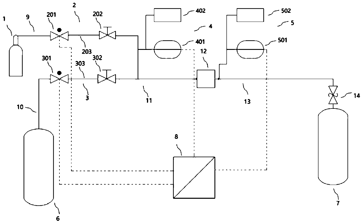
[0022] figure 1 Shown is an automatic airtight test system according to an embodiment of the present invention, wherein the test system includes a gas source 1, a first valve assembly 2, a second valve assembly 3, a first detection assem...


PUM


Abstract

The invention provides an automatic gas-tight testing system. The testing system comprises a gas source, a first valve module, a second valve module, a first detection module, a second detection module, a first gas cylinder, a second gas cylinder, a control unit, a first pipeline, a second pipeline, and a tee pipeline; the gas source communicates with the first valve module through a first pipeline, the first gas cylinder communicates with the second valve module through a second pipeline; a first end of the tee pipeline communicates with the first valve module, a second end of the tee pipeline communicates with the second valve module, and a third end of the tee pipeline communicates with the second gas cylinder; the first detection module is arranged on any end of the tee pipeline, the second detection module is arranged at an opening of the second gas cylinder, and the control unit is electrically connected with the first valve module, the second valve module, the first detection module and the second detection module. The testing system provided by the invention has the advantages that the testing gas is recycled, the automation degree is high, and the gas charging speed is fast.

Description

technical field [0001] The invention relates to the technical field of fuel cell vehicles, and more specifically relates to an automatic airtight test system. Background technique [0002] A fuel cell vehicle is a vehicle that uses hydrogen instead of traditional petroleum as a power source. It utilizes the oxidation-reduction reaction of hydrogen and oxygen to convert the chemical energy stored in hydrogen into electrical energy while generating a large amount of water, achieving zero pollution and zero emissions to the environment. It is the mainstream direction of the world's automobile development. However, due to the small molecular weight of hydrogen and its high permeability, it is easy to diffuse and has strong flammability and explosiveness (explosive limit range of 4% to 74.2% vol in air), once a leak occurs, it is very easy to cause an explosion hazard. Therefore, in the production and use process of the fuel cell vehicle hydrogen storage and supply system, the a...

Claims


Application Information

Patent Timeline
Patent Type & Authority Applications(China)
IPC IPC(8): G01M3/32
Inventor 李想张国强刘萍
Owner BEIJING SINOHYTEC
Learn More