A slidable and rotatable plug-in device

A plug-in and slide-way technology, applied in the direction of coupling device, connecting device parts, connecting parts installation, etc., can solve the problems of plug wire damage, inability to adjust the angle, unsafe, etc., to prolong the service life and avoid short-circuit conditions. , the effect of low cost

Active Publication Date: 2020-05-22
临沭县独沭一帜富华商贸有限公司
View PDF10 Cites 0 Cited by
  • Summary
  • Abstract
  • Description
  • Claims
  • Application Information

AI Technical Summary

Problems solved by technology

More than one power plug can be connected, which not only saves space but also saves lines. At present, desks are generally in the form of facing each other, that is, two people sit face to face on a table, and they need to supply power to computers, mobile phones and other electrical appliances. There are many defects. The plug of the plug-in board is generally inserted into the ground, and the power cord of the plug-in board is generally too long or too short to connect to the power supply or electrical appliances. Sometimes, multiple plug-in boards are required to connect and use, resulting in chaos. , it is extremely inconvenient to use, and it is neither safe nor beautiful to place on the ground. Usually, the power supply of the plug-in disk will be cut off when off work. Moreover, the plug-in strip is in a fixed direction, and the angle cannot be adjusted. It is not convenient for multiple people to use it at the same time. A long time will cause damage to the plug and wire, resulting in the scrapping of the power connector.

Method used


Image

  • A slidable and rotatable plug-in device
  • A slidable and rotatable plug-in device
  • A slidable and rotatable plug-in device

Examples


Embodiment Construction

[0014] The present invention will be further elaborated below in conjunction with the accompanying drawings and specific embodiments.

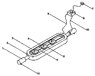
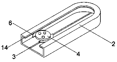
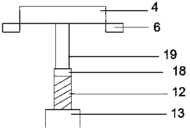
[0015] like figure 1 , figure 2 , image 3 , Figure 4 As shown, a slidable and rotatable plug-in device includes: a telescopic rod 1, a fixed box 2, a slideway 3, a movable insert plate 4, an internal threaded interface 5, a contact copper sheet 6, a plug 7, a switch button 8, Live wire 9, neutral wire 10, outer sleeve 11, spring 12, draw-in groove 13, copper bar 14, handle 15, spring sleeve 16, spring A17, bearing 18, rotating shaft 19, the two ends of described fixed box 2 are installed with Telescopic rod 1, the slideway 3 is installed on the inner bottom surface of the fixed box 2, copper strips 14 are fixed on the bottom of the upper surface on both sides of the upper surface of the fixed box 2, and the two ends of the copper strips 14 are respectively provided with internal threads Interface 5, the bottom of the movable insert 4 is...


PUM


Abstract

The invention relates to a slidable and rotating arranging device. The slidable and rotating arranging device comprises telescopic rods, a fixed box, a slide rail, a moving insertion pad, an internalthread interface, a contact copper piece, a plug, a switch button, a fire wire, a neutral wire, an outer sleeve, a spring, a neck, copper strips, a handle, a spring sleeve, a spring A, a bearing and arotating shaft. The two ends of the fixed box are provided with the telescopic rods, the slide rail is installed at the bottom surface of the internal portion of the fixed box, the copper strips arefixed at the bottom portion of the upper edge of two sides of the upper surface of the fixed box, the bottom portion of the moving insertion pad is connected with the contact copper piece configured to connect with the power source, the bearing is installed at the bottom portion of the moving insertion pad, the moving insertion pad is installed on the slide rail through the neck at the bottom portion, and the spring sleeve and the fixed box are integrally formed. The device is beautiful and methodical in distribution, safe and reliable and very convenient and rapid to cut off the power sourceat the desktop, can be made of plastic materials in the whole external portion, is low in cost and is suitable for popularization and application.

Description

technical field [0001] The invention relates to the field of office supplies, in particular to a slidable and rotatable plug-in device. Background technique [0002] The plug-in strip is a multi-position socket with wires, commonly known as a plug-in board, a plug-in strip, and the scientific name is a wire extension component or an extension cord socket. The socket refers to a multi-position socket with a power cord and a plug that can be moved. More than one power plug can be connected, which not only saves space but also saves lines. At present, desks are generally in the form of facing desks, that is, two people sit face to face on a desk, and they need to supply power to computers, mobile phones and other electrical appliances. There are many defects. The plug of the plug-in board is generally inserted into the ground, and the power cord of the plug-in board is generally too long or too short to connect to the power supply or electrical appliances. Sometimes, multiple ...

Claims


Application Information

Patent Timeline
Patent Type & Authority Patents(China)
IPC IPC(8): H01R27/00H01R13/514H01R13/73H01R13/70
Inventor 陈祥郝茂芝
Owner 临沭县独沭一帜富华商贸有限公司
Why Eureka
Try Eureka