Input device detection system and method thereof

An input device and detection system technology, applied in the detection of faulty computer hardware, etc., can solve problems such as the mouse is not correctly placed in the detection area, wrong detection results, etc., to improve accuracy and reliability, and avoid offset Effect

Inactive Publication Date: 2019-05-07
PRIMAX ELECTRONICS LTD
View PDF6 Cites 0 Cited by
  • Summary
  • Abstract
  • Description
  • Claims
  • Application Information

AI Technical Summary

Problems solved by technology

However, when the inspector puts the mouse into the jig, it often happens that the mouse is not correctly placed in the detection area, or the mouse is not placed in a horizontal state, which leads to false detection results
[0004] In view of this, when the optical or laser sensing module of the input device performs detection, how to avoid the generation of false detection results due to incorrect positioning of the input device, and at the same time improve the accuracy and reliability of the detection results is an important aspect of the present invention. Technical issues to be solved

Method used


Image

  • Input device detection system and method thereof
  • Input device detection system and method thereof
  • Input device detection system and method thereof

Examples


Embodiment Construction

[0086] The advantages and features of the present invention and methods for attaining the same will be more easily understood by more detailed description with reference to exemplary embodiments and accompanying drawings. However, the invention may be embodied in different forms and should not be construed as limited to the embodiments set forth herein. On the contrary, for those skilled in the art, these embodiments are provided to make this disclosure more thorough, comprehensive and fully convey the scope of the present invention.

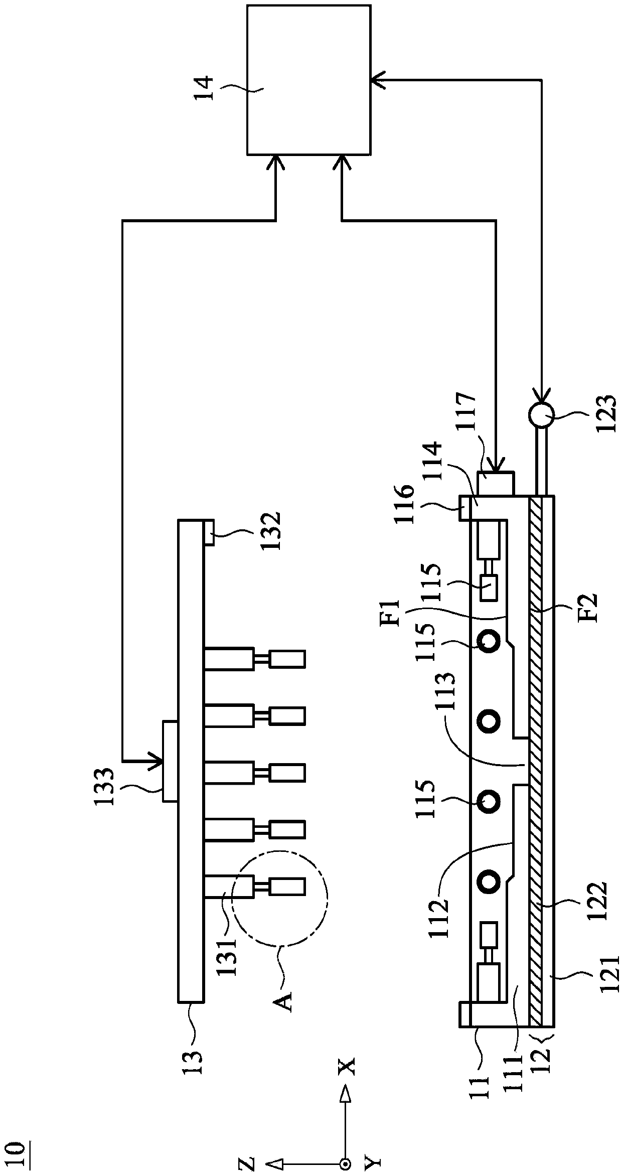
[0087] First, see Figure 1A as shown, Figure 1A An input device detection system provided by the present invention. The input device detection system 10 is used to detect an input device with an optical sensing module, such as a mouse. The input device detection system 10 includes: a base 11 , a trajectory detection board 12 , a cover 13 and a control device 14 . The control device 14 can connect the base 11, the track detection board 12, and...


PUM


Abstract

The invention provides an input device detection system and method, and the system comprises a pedestal which comprises a bottom plate which is provided with an upper surface, a lower surface, and a detection opening; a frame formed on the upper surface; a first telescopic rod which is formed on the inner edge of the frame and used for pushing and fixing the input device in the horizontal direction; a cover plate which is provided with a second telescopic rod and used for pushing and fixing the input device in the vertical direction; and a track detection plate which is arranged below the bottom plate and is adjacent to the lower surface; wherein the optical sensing module of the input device is used for generating a light beam, the light beam passes through the detection opening and is projected to the track detection plate, and the track detection plate moves relative to the base and reflects the light beam to the optical sensing module, so that the input device generates a track signal. The first telescopic rod and the second telescopic rod are used for pushing the input device, the input device is stably and accurately positioned in the detection area of the base, the input device is prevented from deviating in the detection process, and the accuracy and credibility of the detection result of the input device are improved.

Description

technical field [0001] The invention relates to the application field of a detection system, in particular to a detection system of an input device and a method thereof. Background technique [0002] An input device, such as a mouse, is used to control a cursor on a computer screen and thereby operate the computer. Since the United States produced the world's first mouse in 1968, the mouse has become an indispensable part of computer equipment, whether it is word processing, video game competition, industrial drawing, design drawing or media production. Early mouse used the trackball to detect the mouse displacement. With the advancement of technology and to improve its work efficiency, it has gradually evolved into the form of using optical or laser sensing modules for displacement detection. [0003] During the manufacturing process of the mouse, the mouse is placed in jigs with different detection surfaces, and by moving the mouse or the detection surfaces in the jig, it...

Claims


Application Information

Patent Timeline
IPC IPC(8): G06F11/22
Inventor 蔡正壹曾英哲
Owner PRIMAX ELECTRONICS LTD
Why Eureka
Try Eureka