Low-nitrogen gas burner achieving automatic adjustment of flame shape

A gas burner and automatic adjustment technology, applied in the directions of gas fuel burners, burners, combustion methods, etc., can solve the problems of mismatched flame shapes of new burners, furnace surge, limited adjustment amount, etc., to improve safety. and economy, eliminate residual rotation, realize the effect of real-time adjustment

Pending Publication Date: 2019-05-07
XIAN TPRI BOILER ENVIRONMENTAL PROTECTION ENG CO LTD
View PDF0 Cites 7 Cited by
  • Summary
  • Abstract
  • Description
  • Claims
  • Application Information

AI Technical Summary

Problems solved by technology

However, in the process of replacing the burner, it is inevitable that the flame shape (length, diameter) of the new burner does not match the original boiler, resulting in unstable combustion and surge in the furnace, and in severe cases, even the flame cannot be formed
To solve the above problems, some existing products are equipped with an outer air duct that can be pulled back and forth along the axial direction of the burner, and some are equipped with a swirling air distribution disc that can be pulled back and forth along the axial direction. Both types of products are limited by the distance between the fuel nozzle and the combustion air outlet. However, the amount of adjustment is extremely limited, and it will lead to unstable combustion and increased NOx and carbon monoxide (CO) production due to too early or too late air supply
In addition, large gas-fired boilers usually have two or more burners in a single furnace according to different capacities. The necessity of adjusting the flame shape of the burners in such boilers is not only reflected in the above problems, but more importantly, by The direction of rotation is used to eliminate the residual rotation in the furnace to ensure uniform load on the heating surface, which cannot be achieved by axially adjusting the position of the air cylinder or swirl disc

Method used


Image

  • Low-nitrogen gas burner achieving automatic adjustment of flame shape
  • Low-nitrogen gas burner achieving automatic adjustment of flame shape
  • Low-nitrogen gas burner achieving automatic adjustment of flame shape

Examples


Embodiment Construction

[0023] The present invention is described in further detail below in conjunction with accompanying drawing:

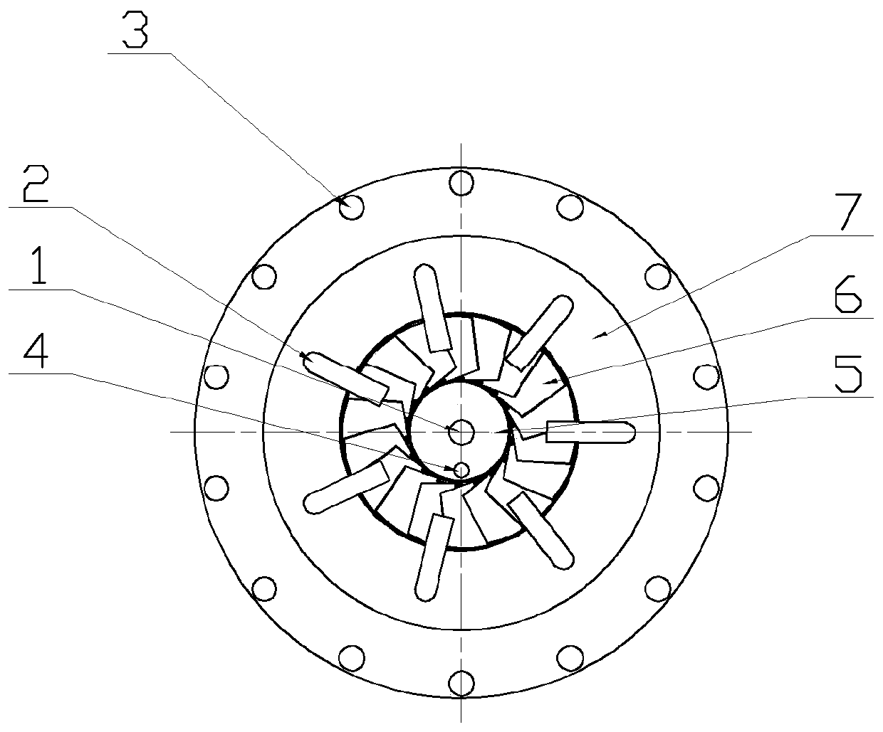
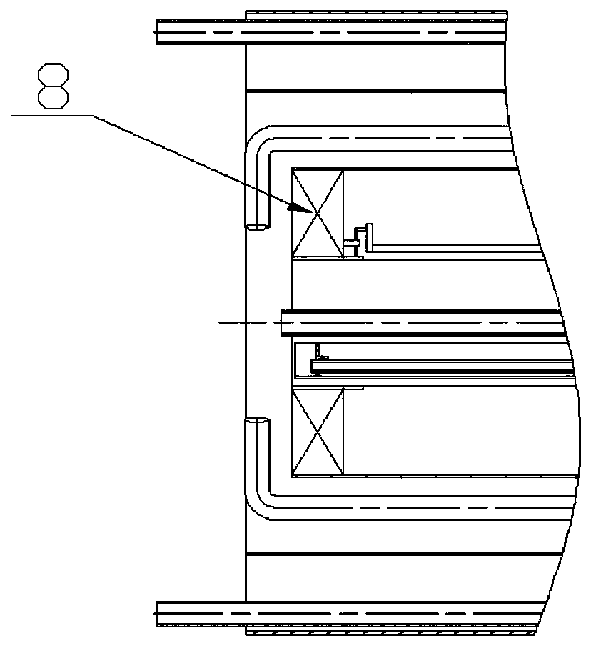
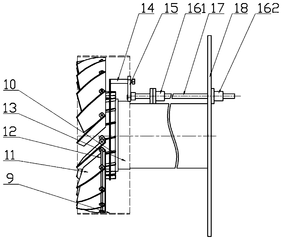
[0024] refer to figure 1 , figure 2 and image 3 , the low-nitrogen gas burner with automatic flame shape adjustment according to the present invention includes an inner air duct 13, an outer air duct 9, a casing, a swirl disc 8, an actuator, several primary fuel spray guns 1, several ignition spray guns 4, several The secondary fuel spray gun 2 and several tertiary fuel spray guns 3; the inner air cylinder 13, the outer air cylinder 9 and the casing are empty from the inside to the outside in turn, and the primary air passage 5 is formed in the inner air cylinder 13, and the inner air cylinder 13 and the outer air cylinder The secondary air passage 6 is formed between the air cylinders 9, the tertiary air passage 7 is formed between the outer air cylinder 9 and the box shell, the secondary air passage 6 is provided with a swirl disc 8, the primary fuel spray gun 1 ...


PUM


Abstract

The invention discloses a low-nitrogen gas burner achieving automatic adjustment of the flame shape. A secondary air channel is formed between an inner air duct and an outer air duct, and a tertiary air channel is formed between the outer air duct and a box shell. A rotational flow disc is arranged in the secondary air channel, a primary fuel spray gun and an ignition spray gun are located in a primary air channel, secondary fuel spray guns are located in the secondary air channel, and tertiary fuel spray guns are located between the tertiary air channel and the box shell. Rotational flow blades are located outside the inner air duct, one rotating shaft corresponds to one rotational flow blade, the ends of the rotating shafts are fixed to an inner barrel of the rotational flow disc, and the rotational flow blades are fixed to the corresponding rotating shaft. Strip-shaped poking pieces are arranged on the roots of the rotational flow blades and connected with a poking disc, and an actuator is connected with the poking disc through a transmission shaft. The low-nitrogen gas burner can adjust the flame shape and the air quantity ratio according to the size of a boiler furnace.

Description

technical field [0001] The invention belongs to the technical field of ultra-low-nitrogen clean burners, and relates to a low-nitrogen gas burner with automatic adjustment of flame shape. Background technique [0002] At present, gas burners are mainly divided into premixed burners and non-premixed burners. The non-premixed burners all adopt the swirling air distribution combustion technology to form a recirculation area in the center of the flame to achieve smoke and strengthen The effect of air-fuel mixing, this technology can effectively reduce the generation of nitrogen oxides (NOx) in combustion. [0003] In recent years, with the implementation of the latest "Emission Standard of Air Pollutants" (GB13223-2011) and local "standards", the NOx emission limit of power plants and industrial boilers in my country has reached 30mg / m 3 (Standard state, reference oxygen content 3%) is the most stringent index in history, and the traditional burner is facing a comprehensive rep...

Claims


Application Information

Patent Timeline
Patent Type & Authority Applications(China)
IPC IPC(8): F23D14/24F23D14/84
Inventor 师云泽申继康姬海民徐党旗周飞梁双轨
Owner XIAN TPRI BOILER ENVIRONMENTAL PROTECTION ENG CO LTD
Why Eureka
Try Eureka