
A precision pointing platform based on flexible parallelogram mechanism

A parallelogram and flexible technology, applied in the direction of machine/support, supporting machine, mechanical equipment, etc., can solve the problems of output platform rotation center drift, driver harmful lateral motion isolation, axial and lateral parasitic motion, etc. Achieve the effect of avoiding temperature drift error, reducing adverse effects, and reducing lateral displacement transmission

Active Publication Date: 2021-04-06
BEIJING MECHANICAL EQUIP INST
View PDF9 Cites 0 Cited by
  • Summary
  • Abstract
  • Description
  • Claims
  • Application Information

AI Technical Summary

Problems solved by technology

[0005] However, the existing precision flexible pointing platforms mostly use simple multi-axis hinge joints (such as omnidirectional notch hinges or series reed hinges) for their flexible support structures, and the rotation guidance of pointing motion only depends on the elongation or extension of the control driver. Shorten the implementation, the output platform pointing to the platform can experience unwanted axial and lateral parasitic motion
The reason for this is that the output platform pointing to the platform lacks a fixed center of rotation, which will drift due to changes in the drive input
In addition, since the piezoelectric ceramic driver is directly connected to the multi-axis hinge joint, as the rotation angle of the output platform increases, the lateral force of the driver will become larger and larger, and it will easily exceed its lateral shear force limit, causing damage to the driver. destroy
In the final analysis, the existing precision flexible pointing platform lacks an effective pointing motion guiding mechanism, resulting in the drift of the rotation center of the output platform, and the driver does not effectively isolate the harmful lateral motion

Method used


Image

  • A precision pointing platform based on flexible parallelogram mechanism
  • A precision pointing platform based on flexible parallelogram mechanism
  • A precision pointing platform based on flexible parallelogram mechanism

Examples


Embodiment Construction

[0045] Preferred embodiments of the present invention will be described in detail below in conjunction with the accompanying drawings, wherein the accompanying drawings constitute a part of the application and together with the embodiments of the present invention are used to explain the principle of the present invention and are not intended to limit the scope of the present invention.

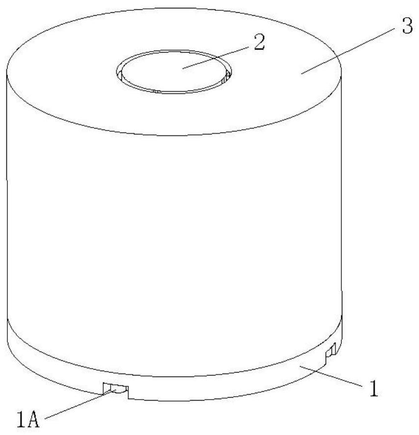
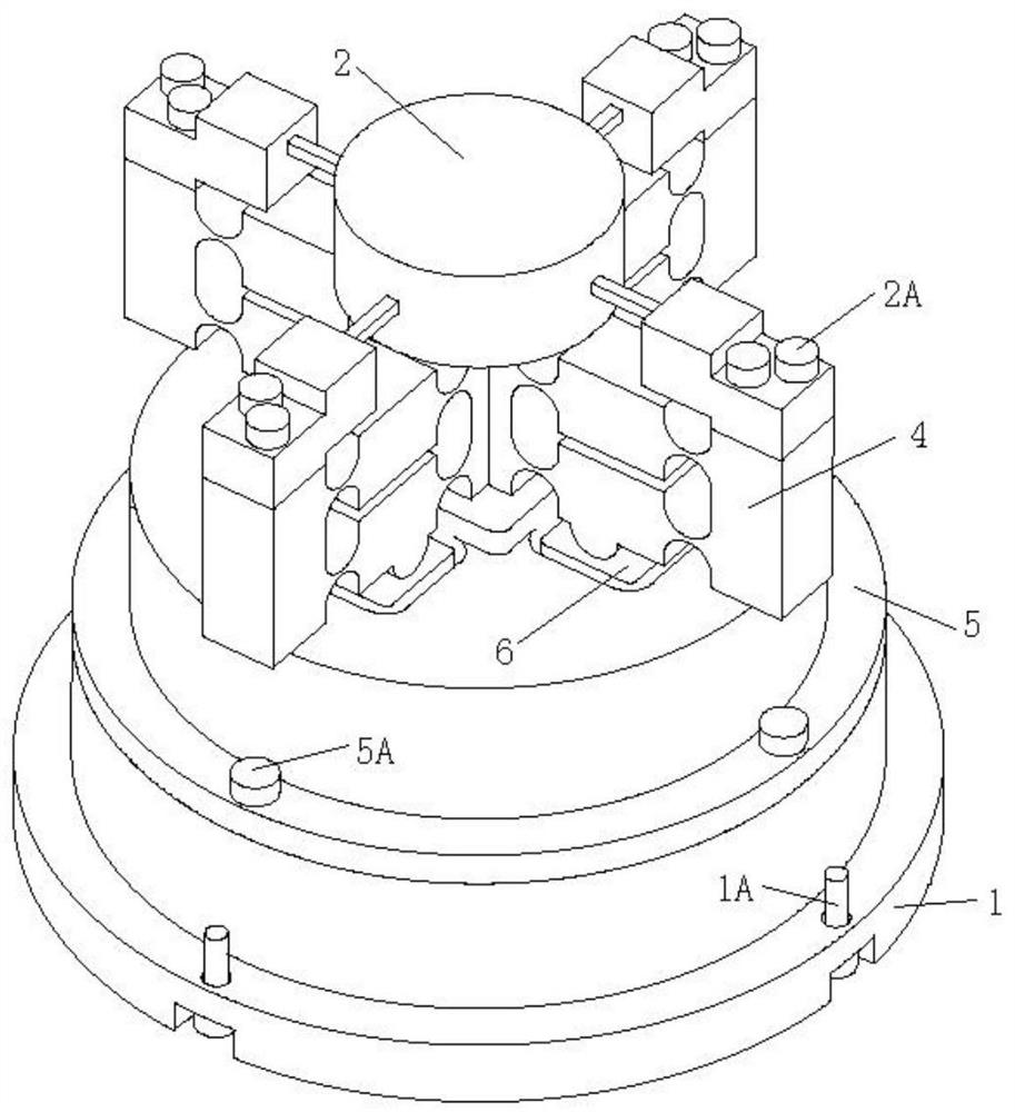
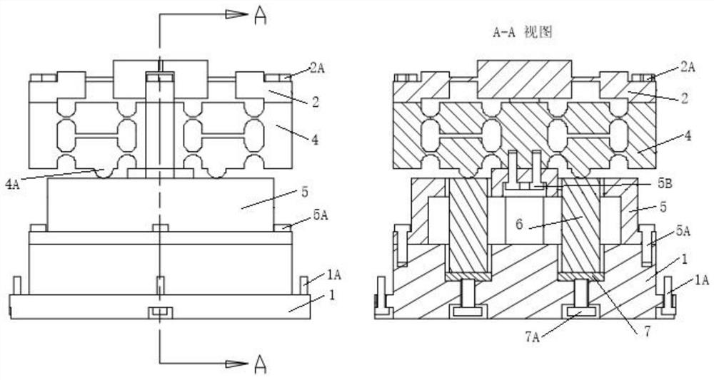
[0046] The object of the present invention is to provide a precision pointing platform device based on a flexible parallelogram mechanism. The precise pointing platform device can complete the two-dimensional deflection function in space. The invention adopts a piezoelectric ceramic driver as a driving input, and realizes pointing motion guidance by constructing a flexible parallelogram rotating guide mechanism. The four parallelogram branch chains of the pointing platform are distributed symmetrically at 90°, forming a four-point parallel drive configuration, which can effectively reduce prelo...


PUM


Abstract

The invention relates to a precision pointing platform based on a flexible parallelogram mechanism, which belongs to the field of precision pointing platforms, and solves the problem that the existing precision flexible pointing platform lacks an effective guiding mechanism for pointing motion, which causes the rotation center of the output platform to drift and the driver to be out of alignment. The problem of effective isolation of unwanted lateral motion. The precision pointing platform based on the flexible parallelogram mechanism of the present invention includes: a base assembly, an output platform assembly, an outer sleeve, a parallelogram rotating guide mechanism, an adapter assembly, a piezoelectric ceramic driver and a preload assembly. The precision pointing platform of the present invention adopts a flexible parallelogram mechanism for rotation guidance, and the input end is provided with a convex contact platform, and the output platform has a fixed rotation center. The invention realizes that the rotation center of the output platform does not drift, thereby ensuring stable pointing accuracy, and the convex contact table is arranged at the input end to reduce the adverse influence of lateral load on the piezoelectric ceramic driver.

Description

technical field [0001] The invention relates to the field of precision pointing, in particular to a precision pointing platform based on a flexible parallelogram mechanism. Background technique [0002] The precision pointing platform is widely used in space laser communication, precision capture, aiming and tracking, terrestrial astronomical observation and astronomical telescopes, etc., to realize small-scale, fast and precise pointing and positioning of carrying equipment. The mechanism design of the pointing platform can adopt two design methods: rigid mechanism and compliant mechanism. The kinematic joints of rigid pointing platforms are mostly traditional rigid kinematic pairs, such as gears, bearings, Hooke hinges, spherical joints, etc., which are mostly used in large-angle deflection occasions, such as antenna pointing mechanisms, weapon system fire control, reconnaissance platforms, etc. However, there are inherent nonlinear problems such as friction and backlash ...

Claims


Application Information

Patent Timeline
Patent Type & Authority Patents(China)
IPC IPC(8): F16M11/06F16M11/18G05D3/10
Inventor 屈见亮唐和平田超
Owner BEIJING MECHANICAL EQUIP INST
Learn More