A Valve Actuator with Good Energy Saving Effect

A technology for valve actuators and energy-saving effects, applied to valve details, valve devices, sliding valves, etc., can solve problems such as waste of electric energy, inability to control valve actuators, hidden dangers in production, etc., achieve good sealing effect, avoid waste of electric energy, The effect of easy operation

Active Publication Date: 2020-04-03
兰控阀门执行器江苏有限公司
View PDF8 Cites 0 Cited by
  • Summary
  • Abstract
  • Description
  • Claims
  • Application Information

AI Technical Summary

Problems solved by technology

[0002] Pneumatic actuators are commonly known as pneumatic heads, also known as pneumatic actuators (English: Pneumatic actuator). According to their energy forms, actuators are divided into three categories: pneumatic, electric and hydraulic. They have their own characteristics and are suitable for different occasions. Nowadays, regional valves Valves such as four-port three-way valves and sub-collectors are widely used in water and gas transportation fields such as building air-conditioning systems and heating systems. Control, many factories need valve actuators to control the pipeline, but today's valve actuators need to be continuously pushed by electric push rods to keep the valve actuators closed, resulting in a large waste of electric energy, and when there is an unexpected power failure At this time, it is impossible to control the valve actuator, resulting in the stoppage of the factory operation, and at the same time causing hidden dangers in production

Method used


Image

  • A Valve Actuator with Good Energy Saving Effect
  • A Valve Actuator with Good Energy Saving Effect
  • A Valve Actuator with Good Energy Saving Effect

Examples


Embodiment Construction

[0019] The following will clearly and completely describe the technical solutions in the embodiments of the present invention with reference to the accompanying drawings in the embodiments of the present invention. Obviously, the described embodiments are only some, not all, embodiments of the present invention. Based on the embodiments of the present invention, all other embodiments obtained by persons of ordinary skill in the art without making creative efforts belong to the protection scope of the present invention.

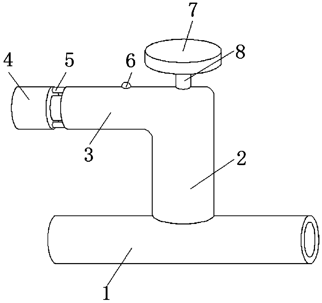
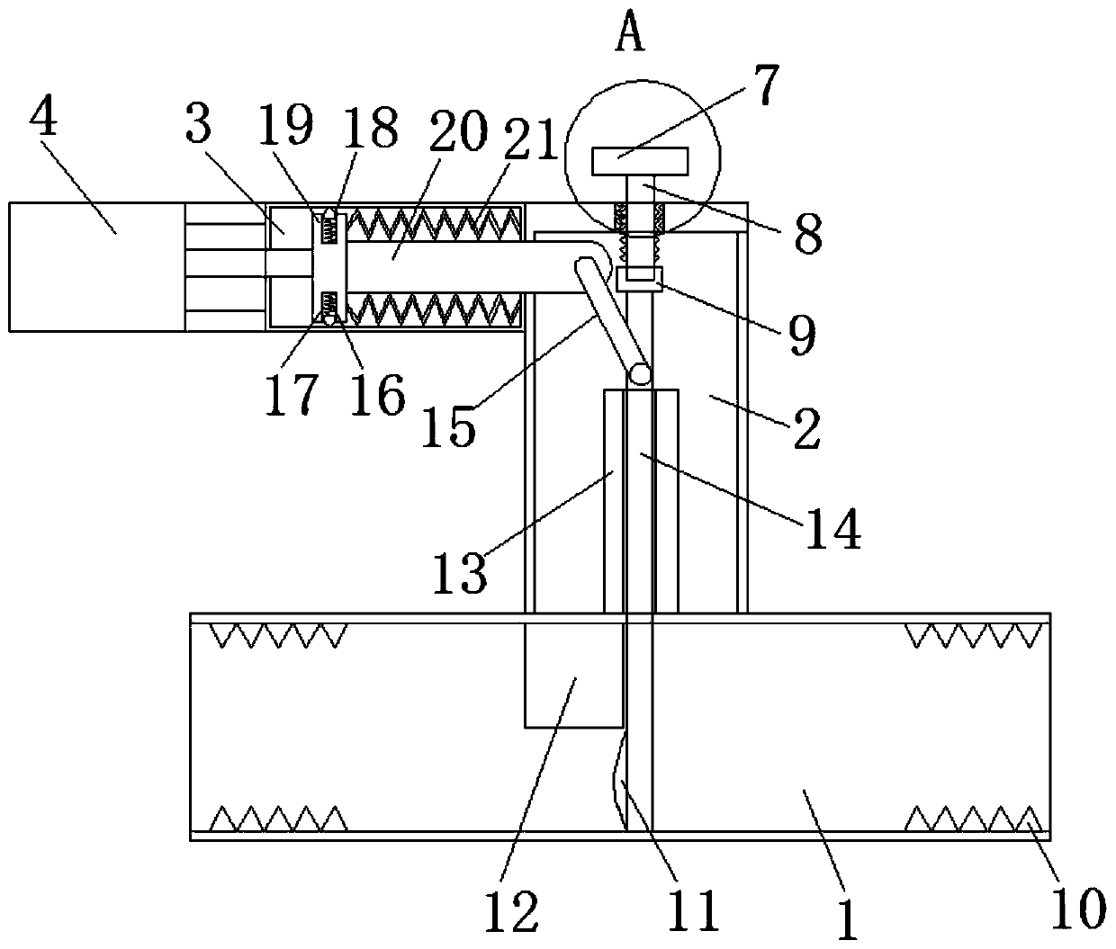
[0020] see Figure 1-5 , an embodiment provided by the present invention: a valve actuator with good energy-saving effect, including a pipe body 1, a fixed pipe 2 is arranged at the middle position of the top of the pipe body 1, and a sleeve is fixed on the top of one side of the fixed pipe 2. Sleeve 3, one side of the fixed sleeve 3 is fixed with an electric push rod 4 (model GRA-L36) through the installation rod 5, and the upper and lower ends of the sleeve ...


PUM


Abstract

The invention discloses a valve actuator with good energy-saving effect. The valve actuator comprises a pipe body, a fixing pipe is arranged at the middle position of the top of the pipe body, moreover, a sleeve is fixed at the top end of one side of the fixing pipe, an electric push rod is fixed on one side of the fixing sleeve through a mounting rod, moreover, clamping grooves are formed in theupper end and the lower end of the sleeve, and a push plate is arranged at the output end of the electric push rod. According to the valve actuator, the arranged electric push rod pushes the push plate to move, the push plate drives a connecting rod to move, under cooperation between a movable arm and a limiting plate, a sliding rod moves downwards, then the purpose of blocking the pipe body is achieved, first reset springs drive clamping heads to enter the clamping grooves while blocking is performed, so that fixation of the push plate is completed, then electric energy waste caused by the fact that the electric push rod is continuously used is avoided, an arranged rotating handle drives a screw column to continuously move downwards under the condition that a second internal thread and asecond external thread cooperate with each other, and the screw column drives the sliding rod to move downwards under the action of a rotating disc to achieve the purpose of manual on-off.

Description

technical field [0001] The invention relates to the field of valve actuators, in particular to a valve actuator with good energy-saving effect. Background technique [0002] Pneumatic actuators are commonly known as pneumatic heads, also known as pneumatic actuators (English: Pneumatic actuator). According to their energy forms, actuators are divided into three categories: pneumatic, electric and hydraulic. They have their own characteristics and are suitable for different occasions. Nowadays, regional valves Valves such as four-port three-way valves and sub-collectors are widely used in water and gas transportation fields such as building air-conditioning systems and heating systems. Control, many factories need valve actuators to control the pipeline, but today's valve actuators need to be continuously pushed by electric push rods to keep the valve actuators closed, resulting in a large waste of electric energy, and when there is an unexpected power failure At this time, ...

Claims


Application Information

Patent Timeline
Patent Type & Authority Patents(China)
IPC IPC(8): F16K31/44F16K3/02F16K3/312F16K31/05F16K31/50
Inventor 张玉鑫吴鹏贾正晨吴宁宁张玉兵
Owner 兰控阀门执行器江苏有限公司
Why Eureka
Try Eureka