
UAV test platform

A test platform and unmanned aerial vehicle technology, applied in the field of unmanned aerial vehicles, can solve the problems of slow wireless transmission signal transmission speed, size limitation of the tested unmanned aerial vehicle, increased test cost, etc., to overcome the slow and reliable wireless transmission signal rate Real-time data transmission channel, efficient and accurate receiving and sending effect

Active Publication Date: 2021-05-18
WUHAN UNIV OF SCI & TECH
View PDF6 Cites 0 Cited by
  • Summary
  • Abstract
  • Description
  • Claims
  • Application Information

AI Technical Summary

Problems solved by technology

At present, the existing unmanned test requires a relatively large site. When the drone is running, it is difficult to accurately observe the attitude and motion performance of the drone itself; the drone and the ground station are generally connected wirelessly, which is limited by wireless transmission signal transmission. The status quo of slow speed and susceptible to interference makes it difficult to obtain and observe detailed flight data of UAVs in real time, resulting in greatly reduced test efficiency
Most of the existing UAV test platforms are relatively heavy and inconvenient for testers to operate, and there is a certain size limit for the UAV under test, which lacks versatility
In addition, current drones generally use their own dedicated lithium batteries for power supply. The flight time is limited by the power of lithium batteries. Long-term tests require multiple battery replacements, which affects test efficiency. Moreover, large-capacity lithium batteries are expensive, so prepare multiple lithium batteries. The battery will increase a lot of testing costs

Method used


Image

  • UAV test platform
  • UAV test platform

Examples


Embodiment Construction

[0020] The specific implementation manners of the present invention will be further described in detail below in conjunction with the accompanying drawings and embodiments. The following examples are used to illustrate the present invention, but are not intended to limit the scope of the present invention.

[0021] In the description of the present invention, it should be noted that the terms "center", "longitudinal", "transverse", "upper", "lower", "front", "rear", "left", "right", " The orientations or positional relationships indicated by "vertical", "horizontal", "top", "bottom", "inner", "outer", etc. are based on the orientation or positional relationships shown in the drawings, and are only for the convenience of describing the present invention and simplifying Describes, but does not indicate or imply that the device or element referred to must have a specific orientation, be constructed in a specific orientation, and operate in a specific orientation, and therefore sh...


PUM


Abstract

The invention relates to the technical field of unmanned aerial vehicles, and discloses an unmanned aerial vehicle test platform, which includes a flange, a rotating bearing, a base and a conductive slip ring. There are mounting holes on the flange for installing the UAV; the flange is installed on the base through a rotating bearing; the conductive slip ring includes a rotor end and a stator end, the rotor end is electrically connected to the UAV, and the stator end is connected to the base . The rotation of the rotating bearing provides the UAV with the degree of freedom required for yaw motion testing; the UAV is connected to the power supply and signal receiving device through a conductive slip ring, so that the UAV can get rid of the limitation of its own limited battery capacity and overcome It overcomes the shortcomings of its own wireless transmission rate, which is slow and susceptible to interference, and can send and receive information efficiently and accurately; the rotor end and stator end of the conductive slip ring can rotate relatively, avoiding the bending and twisting of the transmission wire. The invention provides an efficient and reliable test platform for the unmanned aerial vehicle's yaw movement, and has simple structure, convenient operation and strong practicability.

Description

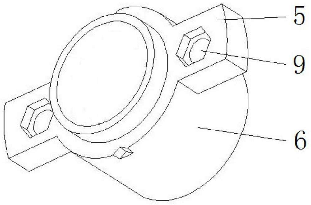
technical field [0001] The invention relates to the technical field of unmanned aerial vehicles, in particular to an unmanned aerial vehicle testing platform. Background technique [0002] With the development of science and technology, drone technology is changing with each passing day. Due to its advantages such as simple landing control and low cost, it is widely used in aerospace, agriculture, military, express delivery and many other industries while satisfying entertainment. In order to improve the stability of the drone's flight control system and ensure the reliable and safe flight of the drone, a lot of testing work is required during the development of the drone. [0003] UAV testing requires platforms that have low space requirements and can test the UAV's attitude adjustment capabilities. At present, the existing unmanned test requires a relatively large site. When the drone is running, it is difficult to accurately observe the attitude and motion performance of...

Claims


Application Information

Patent Timeline
Patent Type & Authority Patents(China)
IPC IPC(8): B64F5/60
Inventor 韩晓林泽彬
Owner WUHAN UNIV OF SCI & TECH
Learn More