
Dynamic groove bearing comprising porous lubricant reservoir

A technology of bearings and grooves, applied in the direction of sliding contact bearings, rotating bearings, bearings, etc., can solve the problems of differences, abnormal operation of grooved bearings, differences, etc., and achieve the effect of easy setting

Inactive Publication Date: 2002-12-25
KONINKLIJKE PHILIPS ELECTRONICS NV
View PDF4 Cites 2 Cited by
  • Summary
  • Abstract
  • Description
  • Claims
  • Application Information

AI Technical Summary

Problems solved by technology

[0005] A disadvantage of this known hydrodynamic grooved bearing is that there may be a difference in the amount of lubricant present in the two porous annular bodies, resulting in a different lubricant supply to the two groove structures, which leads to a non-functional bearing of the grooved bearing. normal operation

Method used


Image

  • Dynamic groove bearing comprising porous lubricant reservoir
  • Dynamic groove bearing comprising porous lubricant reservoir
  • Dynamic groove bearing comprising porous lubricant reservoir

Examples


Embodiment Construction

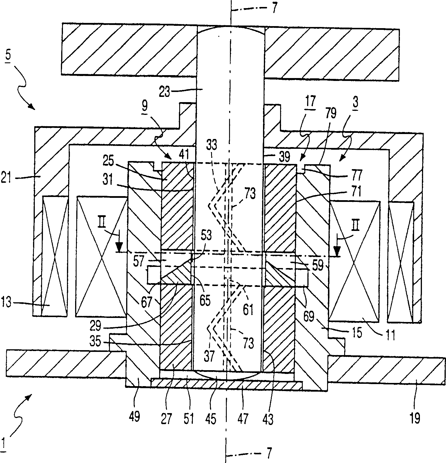
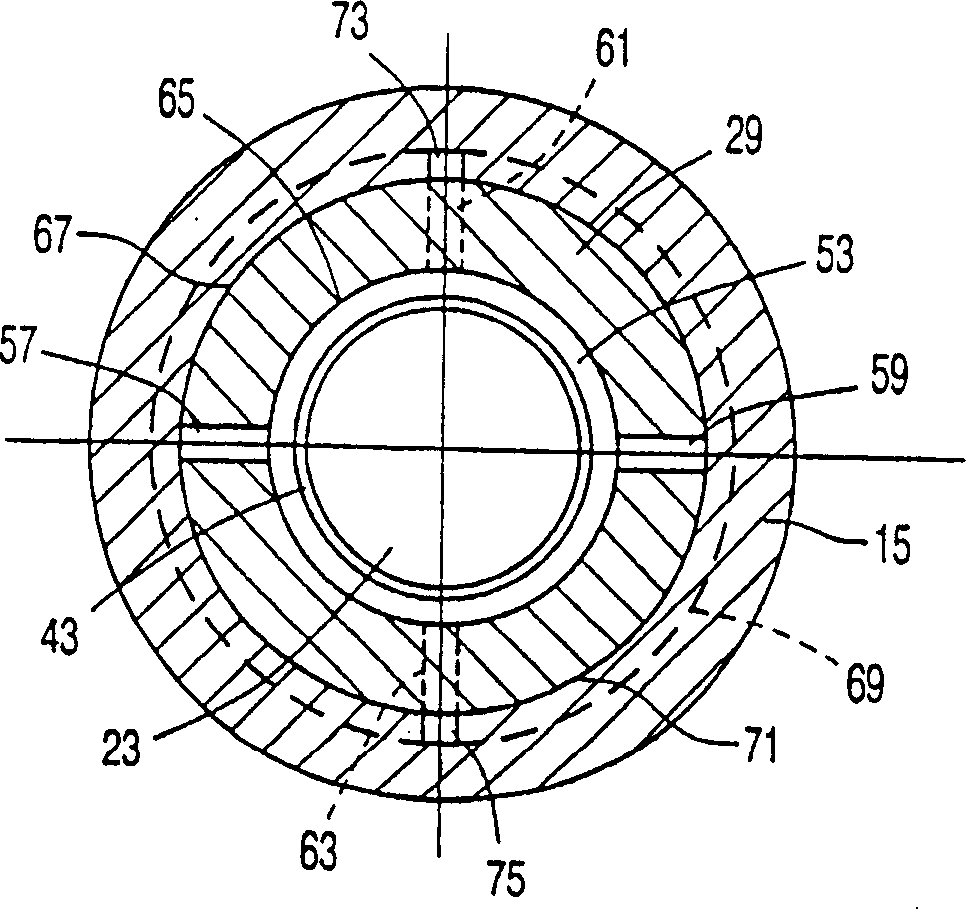
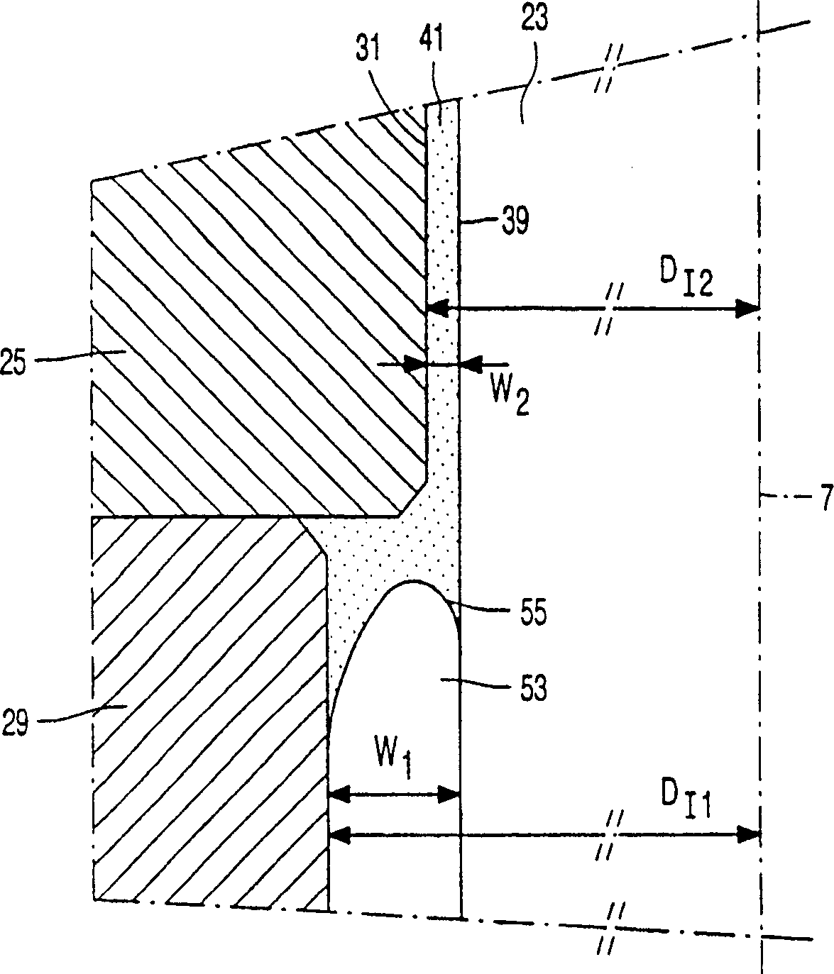
[0022] figure 1 Schematically shows an electric motor 1 according to the invention comprising a stator 3 and a rotor 5 mounted relative to the stator 3 such that the rotor can rotate relative to an axis of rotation 7 via a hydrodynamic grooved bearing 9 according to the invention . Stator 3 contains an electric coil system 11, which coil system in figure 1 is only schematically shown in , while the rotor 5 comprises a permanent magnet system 13 cooperating with an electric coil system 11, in figure 1 is only shown schematically. The electric coil system 11 is fixed to a bush-type bearing housing 15 which forms part of the outer bearing part 17 of the dynamic pressure grooved bearing 9 and which is fixed to the stationary base plate 19 of the electric motor 1 . The permanent magnet system 13 is fixed on an annular magnet support frame 21 which is fixed on a steel shaft 23 . Said shaft 23 forms the inner bearing part of the dynamic pressure grooved bearing 9 and its center l...


PUM


Abstract

The invention relates to a dynamic groove bearing (9) comprising an internal bearing part (23) and an external bearing part (17) which are rotatable relatively to each other about an axis of rotation (7), a bearing surface (31, 35) of one of the bearing parts comprising two grooves for co-operation with a bearing surface (39) of the other bearing part. The groove bearing further comprises a reservoir made from a porous material for a lubricant which is present between the bearing surfaces. According to the invention, the reservoir is mounted between the two groove patterns, viewed in a direction parallel to the axis of rotation. In this manner, a uniform supply of the lubricant from the reservoir to the two groove patterns is obtained, while also the number of parts of the groove bearing is limited. In a preferred embodiment, the reservoir comprises a ring-shaped body (29) which is made from the porous material and mounted in the external bearing part. The ring-shaped body may be confined between two bearing bushes (25, 27) of the external bearing part on which the two groove patterns are present. The ring-shaped body may further comprise at least one air-vent duct (57, 59, 61, 63). The dynamic groove bearing according to the invention can be used in an electric motor (1) for driving a rotatable support (83) for an information carrier (89) in a scanning device (81), such as an optical disc player.

Description

technical field [0001] The present invention relates to a dynamic pressure grooved bearing comprising an inner bearing part and an outer bearing part which are rotatable relative to each other about an axis of rotation, wherein the bearing surface of one bearing part has a bearing surface with the other bearing part Two groove structures mating on the surface, the groove structure is spaced apart when viewed in a direction parallel to the axis of rotation, and the grooved bearing has a reservoir made of porous material for holding lubricant, wherein the lubricating The agent is located between the mating bearing surfaces during operation. [0002] The invention also relates to an electric motor comprising a stator and a rotor, wherein the rotor is mounted to rotate relative to the stator via a dynamic pressure slotted bearing. [0003] The invention also relates to a scanning device provided with a support frame for an information carrier and a scanning unit for scanning the ...

Claims


Application Information

Patent Timeline
Patent Type & Authority Patents(China)
IPC IPC(8): F16C33/10G02B26/12F16C17/02G11B19/20H02K5/16H02K7/08
CPCF16C17/026F16C17/107F16C33/103F16C33/107G11B19/2009H02K5/1675F16C2370/12F16C33/10
Inventor F·布雷默J·M·M·亨辛
Owner KONINKLIJKE PHILIPS ELECTRONICS NV
Learn More