
Method for producing a textile sensor

一种温度传感器、织物的技术,应用在传感器、纺织品和造纸、仪器等方向,能够解决连接困难、线破裂等问题

Inactive Publication Date: 2019-05-03
PLUG & WEAR SRL
View PDF0 Cites 2 Cited by
  • Summary
  • Abstract
  • Description
  • Claims
  • Application Information

AI Technical Summary

Problems solved by technology

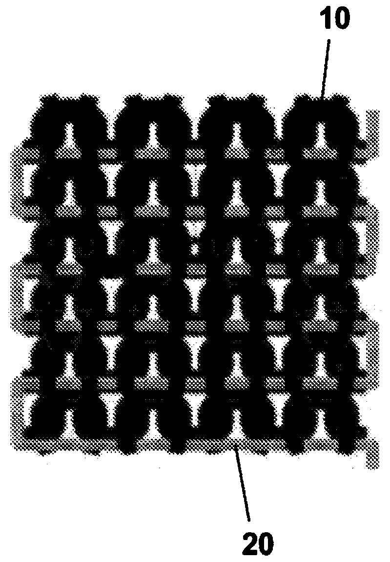
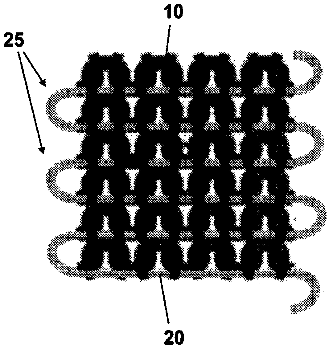
refer to figure 2 A, thus forming side gaps 25 of metal wires 20 protruding from the fabric grain, which, in addition to providing a defect, can cause the wires to break if the side grooves engage some object during the use of the fabric
[0024] Finally, there are difficulties in connecting the ends of the conductive wires to conductive cables with larger diameters that can be used to connect the device to the data acquisition card

Method used


Image

  • Method for producing a textile sensor
  • Method for producing a textile sensor
  • Method for producing a textile sensor

Examples


Embodiment Construction

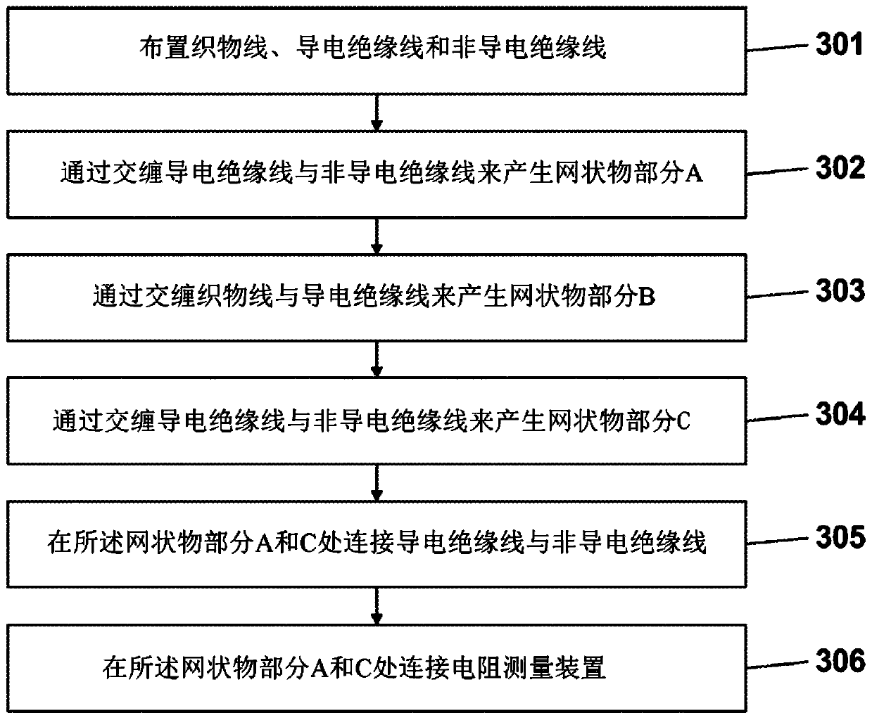
[0076] exist figure 2 The generation according to the present invention is schematically shown in Figure 4 The method steps necessary for the fabric temperature sensor 100.

[0077] Specifically, in a preliminary step [301] of weaving threads 110, electrically conductive insulating threads 120 and non-conductive insulating threads are arranged on respective thread guides of the linear knitting machine. The conductive insulating wire 120 may be, for example, an enamelled copper wire, and the non-conductive insulating wire may be, for example, a soldered copper wire. For example, fabric thread 110 may be a polyester thread.

[0078] Then continue to intertwine the thread. refer to figure 2 with 4 , after generating parts A to C, with the following intertwining steps:

[0079] - part A: intertwining conductive insulating wire 120 with non-conductive insulating wire [302];

[0080] - Part B: intertwining non-conductive insulated wire with fabric wire 110 [303];

[0081] -...


PUM


Abstract

The invention provides a method for manufacturing a textile temperature sensor (100). The method comprises the steps of arranging a linear knitting machine comprising at least one first thread-guide and a second thread-guide; arranging a conductive insulated wire (120) on the first thread-guide, said conductive insulated wire (120) having a first end (121) and a second end (122); meshing the conductive insulated wire (120) for making a mesh portion B having not conductive surface. The method comprises then the steps of arranging an electric resistance measuring device configured to measure a variation of electric resistance R(T), said electric resistance R(T) being function of the temperature T, said step of measuring device phase of the electric resistance comprising a first electric cable (201) and a second electric cable (202); electric connection of the first electric cable (201) to the first end (121) and of the second electric cable (202) to the second end (122); arranging a control unit arranged to receive from the device the variation of electric resistance R(T) in order to calculate excursions of temperature T at the lead wire (120).

Description

technical field [0001] The present invention relates to the field of thermistors, ie temperature sensors that exploit the change in resistance of some materials under temperature changes. [0002] Specifically, the present invention relates to a fabric thermistor. Background technique [0003] A thermistor or resistance thermometer is a temperature sensor that exploits the change in resistance of some materials under temperature changes. [0004] It is also well known that the resistance R developed by a conducting wire when an electric current passes is related to ρ according to the law The resistance of the material, where l e A are the length and section of the conductive wire, respectively. [0005] Also, for metals there is a linear equation relating tolerance to temperature: [0006] ρ(T)=ρ 0 *[1+α(T-T 0 )] [0007] in: [0008] T is the temperature; [0009] ρ(T) is the material’s resistance to temperature T; [0010] ρ 0 is the resistance of the material t...

Claims


Application Information

Patent Timeline
Patent Type & Authority Applications(China)
IPC IPC(8): G01K1/14A41D13/12D04B1/14G01K7/18G01K13/00A61B5/00
CPCA41D13/1281A61B5/6804D04B1/14G01K1/14G01K7/18A61B5/6843A61B5/01A41D1/002D10B2403/02431G01K13/20D04B21/14H01B1/124H01C7/06
Inventor R·马基西
Owner PLUG & WEAR SRL
Learn More